
Whelen CanTrol WC controller
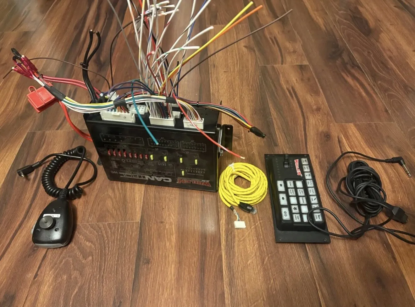
The controller at the center of the build. What the used set is, every pin, how it gets power and ground on a 2015+ F-150, and the rules for programming it.
This page collects the research done on 21 October 2026 before the controller goes on the bench. Every claim carries the same tags the project files use:
| Tag | Meaning |
|---|---|
| Confirmed | Stated in a Whelen or Ford document, or proven on my bench |
| Inferred | Reasoned from the documents, not stated anywhere. The bench test is how it becomes confirmed |
| Seller | Stated by a dealer or reseller listing, not by Whelen |
| General knowledge | Common installer practice, not from a document for this exact part |
Photos of the set
Section titled “Photos of the set”All photos are of my own used set, taken 16 October 2026 when it arrived. The head’s serial-number label is left off the site on purpose.
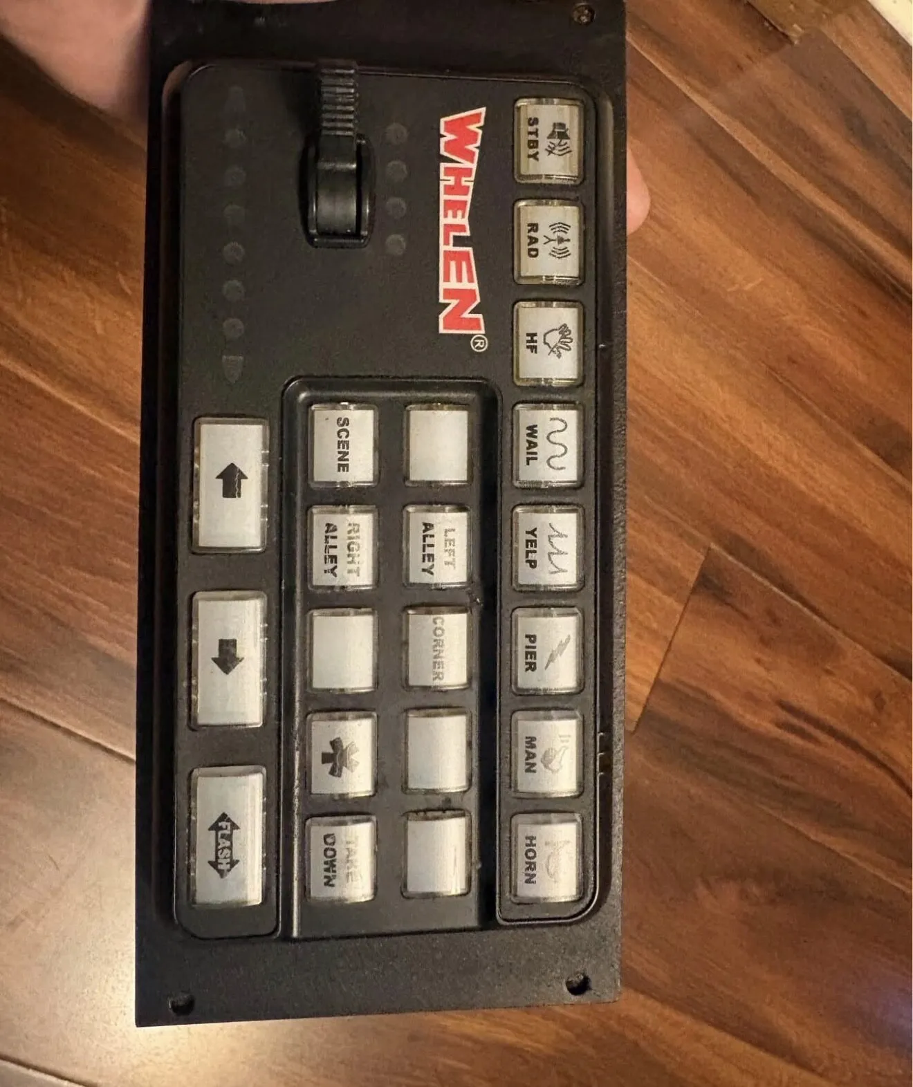
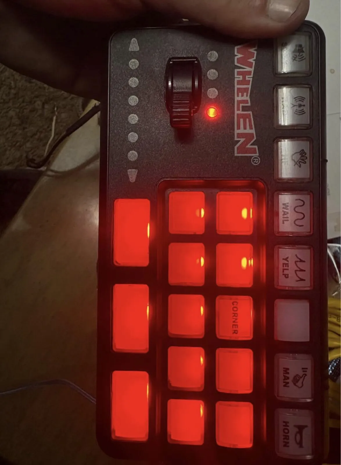
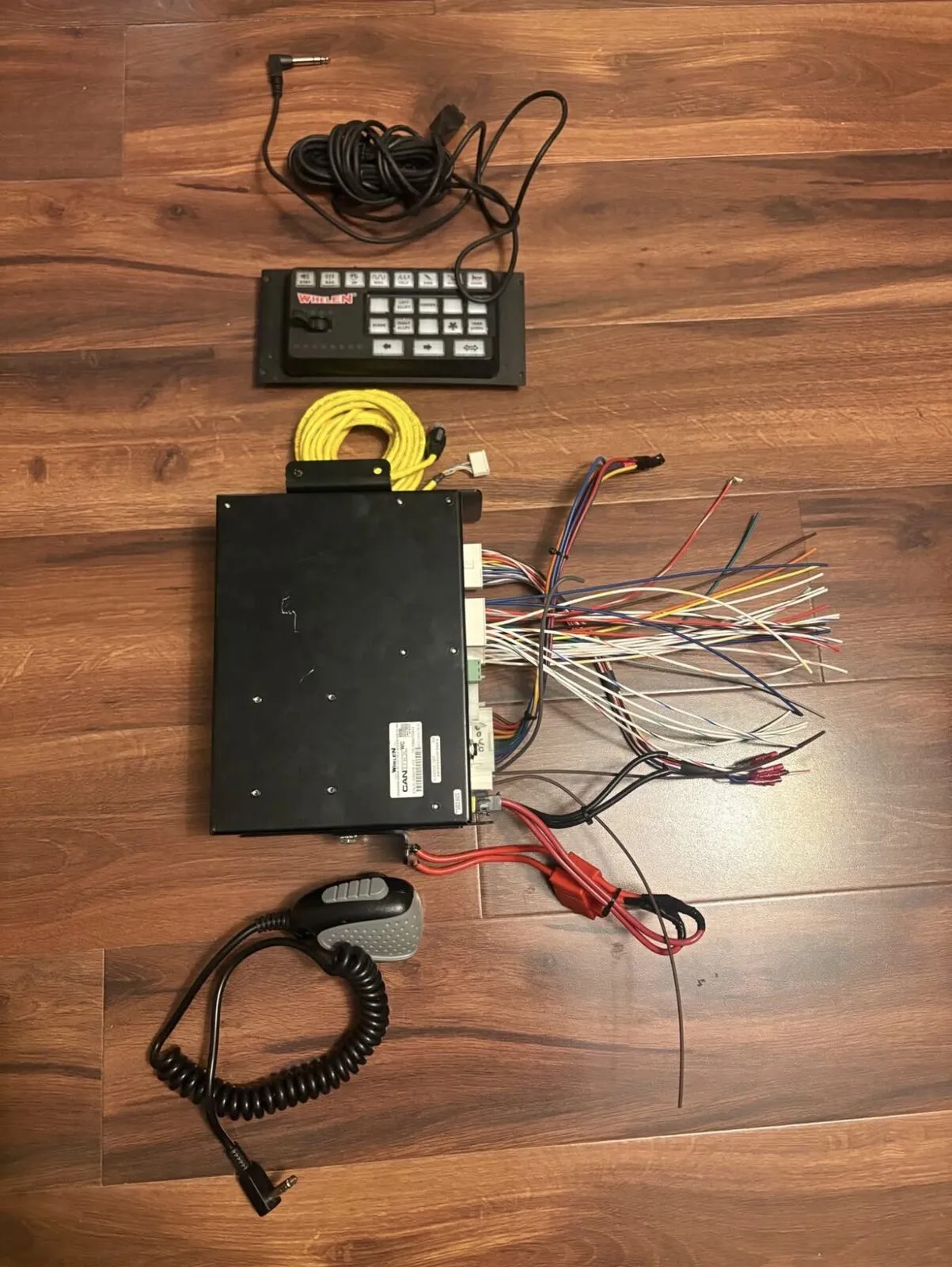
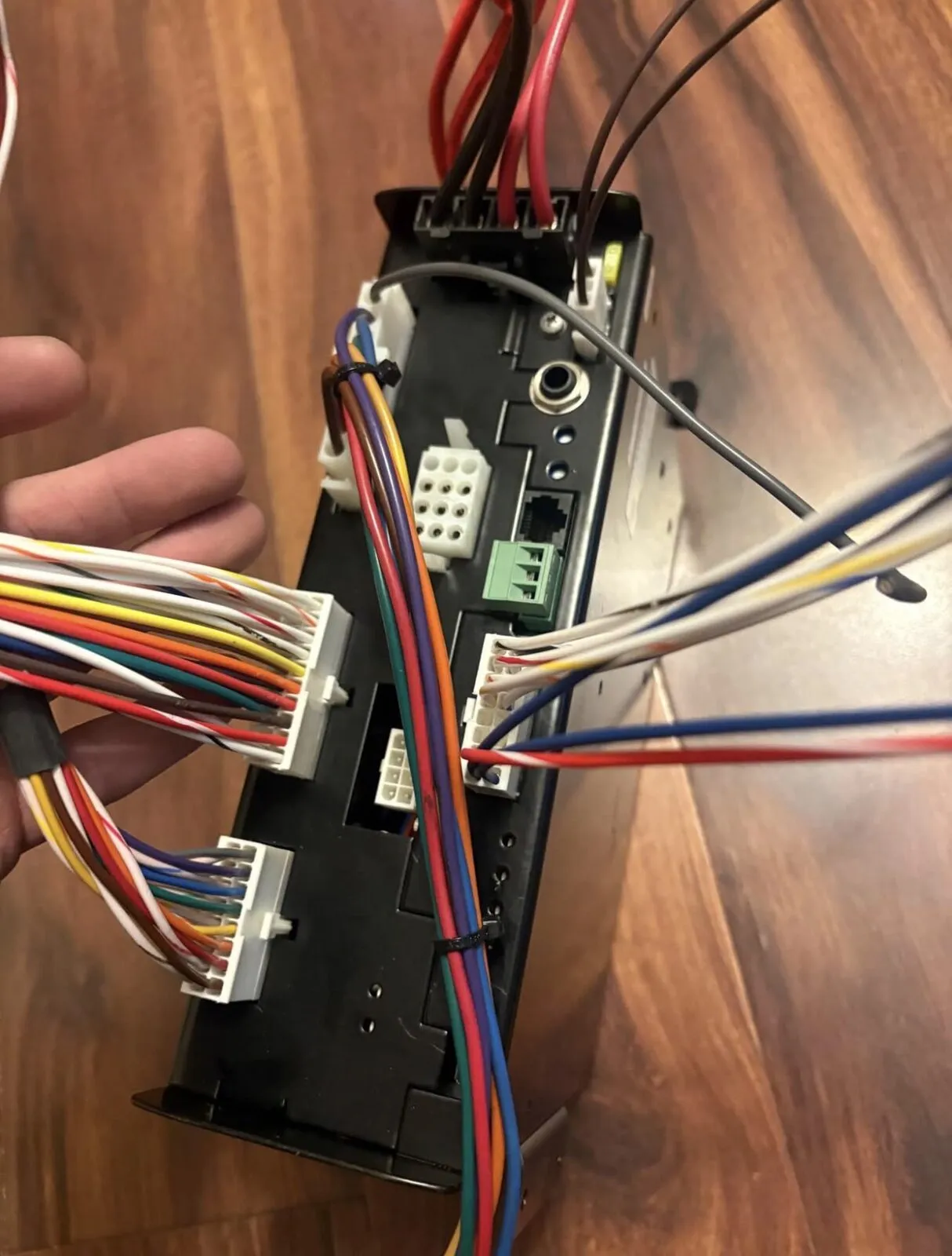
Run every warning light, the siren and the PA from one controller and one control head, with each light keeping its own flash patterns, and with nothing tapped into the truck’s body control module except the Speed Turtle EFM 3.0.
What the controller is
Section titled “What the controller is”Whelen CanTrol WC (used set)
- Bought
- Complete used set: module, 21-button head, mic, cables. $425.00 shipped
- Head label
- WeCan Controller, 21 function w/ slide priority, PN 01-026G550-00C, MFG 01/20
- Head type
- Matches Whelen's CANCTL7 description (21 buttons, 4-position slide) (inferred)
- Module model
- CANWCT2, CANWCT2A or CANWCT3. Label not read yet
- Guide used
- Whelen CanTrol WC Installation/Operating Guide, form 14580G (Feb 2020)
- Programming
- Whelen Command (free, Windows) over USB
- Product status
- Whelen declared WeCan products end of life on 30 June 2025 (advisory MA0082)
Source: Whelen guide 14580G and Whelen price list PL18.1CT
Module family (confirmed from Whelen’s price list)
Section titled “Module family (confirmed from Whelen’s price list)”| Model | What it adds |
|---|---|
| CANWCT2 | Standard amplifier and control module: 32 LED outputs (2.5A), 3 low-current outputs (0.25A), 8 programmable 10A outputs, traffic advisor driver |
| CANWCT2A | CANWCT2 plus an 8-input expansion module |
| CANWCT3 | CANWCT2 plus the CANport OBD-II interface module. This is the only one that can read the brake signal over OBD-II |
Control heads offered with the module: CANCTL4 (6 buttons), CANCTL5 (hand-held), CANCTL6 (8 buttons plus a rotary) and CANCTL7 (3-section head, 21 push-buttons, 4-position slide, mic with extension). The head’s January 2020 date lines up with guide revision 14580G, so that guide’s pinouts are the right reference for this unit (inferred). The seller called it “Gen 3”, which is not a Whelen generation name in any document I found. It may simply mean CANWCT3 (inferred).
Pinout reference
Section titled “Pinout reference”Confirmed from guide 14580G pages 3 to 10 unless marked.
Power and siren
Section titled “Power and siren”| Connector | Pin or lead | Function |
|---|---|---|
| Main power, 4-pin | Pins 1 and 2, black | Ground |
| Main power, 4-pin | Pins 3 and 4, red | +12V in, each fused 40A at the battery. 80A max input |
| Speaker | Pin 1 / orange lead | Speaker high (+) |
| Speaker | Pin 3 / brown lead | Speaker low (−) |
| Module | Siren fuse | 20A |
Standby draw: about 80 mA with ignition on, about 100 microamps with ignition off.
J1 high-current outputs (10A each)
Section titled “J1 high-current outputs (10A each)”| Pin | Lead | Switching |
|---|---|---|
| J1-1 | Brown | Positive only |
| J1-2 | Red | Positive only |
| J1-3 | Orange | Positive only |
| J1-4 | Yellow | Positive only |
| J1-5 | Green | Positive or ground, set by fuse slot |
| J1-6 | Blue | Positive or ground, set by fuse slot |
| J1-7 | Violet | Positive or ground, set by fuse slot |
| J1-8 | Gray | Positive or ground, set by fuse slot |
J4 LED outputs 1 to 16 (2.5A each, internally limited)
Section titled “J4 LED outputs 1 to 16 (2.5A each, internally limited)”| Pin | Output | Lead (guide p.7) | Lead (guide p.10) |
|---|---|---|---|
| J4-3 | 1 | Brown | Brown |
| J4-4 | 2 | Red | Red |
| J4-5 | 3 | Orange | Orange |
| J4-6 | 4 | Yellow | Yellow |
| J4-7 | 5 | White/brown | White/brown |
| J4-8 | 6 | White/red | White/red |
| J4-9 | 7 | White/orange | White/orange |
| J4-10 | 8 | White/yellow | White/yellow |
| J4-13 | 9 | Green | Green |
| J4-14 | 10 | Blue | Blue |
| J4-15 | 11 | Violet | Orange |
| J4-16 | 12 | Gray | Yellow |
| J4-17 | 13 | White/green | White/green |
| J4-18 | 14 | White/blue | White/blue |
| J4-19 | 15 | White/violet | White/orange |
| J4-20 | 16 | White/gray | White/yellow |
LED outputs 17 to 32 are on J2 (J2-1 brown through J2-16 white/gray, same color order). The LED outputs are protected in groups by 20A fuses on the module. All outputs together are limited to 40A.
Low-current, traffic advisor and inputs
Section titled “Low-current, traffic advisor and inputs”| Connector | Pin | Function |
|---|---|---|
| J4 | J4-1 white/black, J4-2 red/white, J4-11 white | LC AUX, 250 mA (J4-1 defaults to horn transfer relay) |
| J10 | J10-1 to J10-8 | Traffic advisor lamps TA1 to TA8, J10-9 white is the +12V common. 20A fuse |
| J17 | J17-1 white/brown | Logic 1, default horn ring (ground activated) |
| J17 | J17-2 white/red | Logic 2, default Park sense (positive, ends siren) |
| J17 | J17-3, -4, -9, -10, -11, -12 | Logic 3 to 8 (1 to 4 positive or negative, 5 to 8 positive only) |
| J17 | J17-5 white/black | Analog 1, default backlight dimmer |
| J17 | J17-7 red/white | Ignition sense (fixed) |
| J17 | J17-8 and J17-16 blue | Radio rebroadcast (fixed) |
Diagnostic LEDs
Section titled “Diagnostic LEDs”| LED | Meaning |
|---|---|
| POW steady | System on |
| ERR steady | Controller bus set to OFF |
| ERR single flash | Bad CanTrol connection |
| ERR double flash | Error control event |
| USB steady | PC connected and ready |
| WC | Relates to a WeCan lightbar. This build has none, so off is expected (inferred) |
Power, grounds and ignition on a 2015+ F-150
Section titled “Power, grounds and ignition on a 2015+ F-150”Main power
Section titled “Main power”Two red leads, each fused 40A within 2 ft of battery positive, on 8 AWG copper. Whelen’s gauge chart allows 8 AWG to 19.5 ft at 40A, and the runs are about 12 ft. 10 AWG would sit right at its 12.5 ft limit, so 8 AWG it is. The fuses go in last, after every circuit is wired (guide p.5).
Grounds: the two rules that override the manuals
Section titled “Grounds: the two rules that override the manuals”- Main grounds: both 8 AWG blacks to the Q-231 ground point, same length as before, no added cost.
- Front devices: a dedicated ground wire to a frame rail side. Whether the grille guard brackets make a good ground path is unknown, so they are not relied on.
- Rear devices: one shared ring terminal on the side of a steel frame rail near the bumper, bare metal, star washer, sealed afterward.
- Module case: Whelen requires the case to be mounted on or grounded to the chassis. Under the rear seat the floor is aluminum, so the case gets a short ground lead to the CanTrol’s own ground run and sits on an isolator, with stainless or coated screws (general knowledge).
Ignition sense (J17-7)
Section titled “Ignition sense (J17-7)”J17-7 has to see +12V only with the key on. The plan uses an add-a-circuit fuse tap. Ford’s body builder guidance says not to tap the interior fuse panel or the under-hood box. The sense wire draws almost nothing, so the electrical risk is low, but it is against Ford’s written guidance. The choice on record is to keep the fuse tap, picking a slot by meter (live in RUN, dead in OFF, never an airbag, engine or brake circuit), unless Ford’s Body Builders Advisory Service names a better source. Fuse numbers are never taken from forums.
Shutdown and key-off draw
Section titled “Shutdown and key-off draw”Whelen Command sets a shutdown delay from Instant up to 4 hours. Ford’s guideline for total key-off draw is 28 mA or less. The CanTrol idles at about 100 microamps with the key off. The Putco remote relay box is on constant 12V and its standby draw is unknown, so it gets measured on the bench.
Inputs left unconnected
Section titled “Inputs left unconnected”| Input | Why |
|---|---|
| J17-5 backlight dimmer | Whelen’s default is a marker-lamp splice, which is a BCM circuit on this truck. Brightness is set in Command instead |
| J17-1 horn ring, J17-2 Park sense | No horn or BCM tap. If the module is a CANWCT3, Park can come from CANport |
| J17-8 / J17-16 radio rebroadcast | Not used. Whelen says it does not work with amplified remote speakers |
The amateur radio stays on its own battery feed and its own ground. Whelen’s guide says never to power warning equipment from the same circuit, or share a ground, with radio equipment (guide p.1). See the Mobile Ham Radio Install.
Siren and speakers
Section titled “Siren and speakers”- Wiring (confirmed): orange to each speaker’s white, brown to each speaker’s black. The second speaker lands on the same two wires. Matched polarity on both, because out-of-phase speakers cancel each other in front of the truck (general knowledge).
- Load: 5.5 Ω minimum. Two 11 Ω UBL 100W speakers in parallel make exactly 5.5 Ω. Never a third speaker. Whelen’s brochure says the CanTrol supports “one or two 100 watt speakers.”
- The 11 Ω figure comes from the speaker listing, not a UBL document I could open. It gets read off the speaker label before wiring. A meter reads DC resistance, so 7 to 9 Ω on an 11 Ω speaker is normal (general knowledge). An 8 Ω rating would put two speakers below Whelen’s minimum.
- Wire: 16 AWG twisted pair to the guard, about 0.12 Ω round trip over 30 ft, roughly 2% of the load (inferred). Kept apart from the head cable and the CANport cable.
- Expected draw: Whelen does not publish the CanTrol’s siren draw. Its 295HFSA6 amp is labeled 8A at 100W and 16A at 200W, so the CanTrol should land in that range (inferred).
Programming rules for Whelen Command
Section titled “Programming rules for Whelen Command”- Start a new configuration. Command cannot extract a legacy CanTrol WC configuration (release notes v1.0.7.0), so the previous owner’s program can’t be pulled. That is fine, because a clean build is the goal anyway.
- Every output that feeds another product’s power or control wire gets Action = Turn On, steady, Low Power disabled. In the current map that is J1-1 to J1-6 and LED 1, 2, 3, 4, 5, 9, 10, 11, 12 and 13. Each light makes its own pattern. A Whelen flash pattern or Low Power on one of those outputs would switch the device on and off or dim its input, so it would misbehave or keep restarting (inferred, bench test each).
- Momentary jobs, like the light bar’s pattern wire on LED 9, use Press On / Release Off.
- Latched jobs (SCENE, arrows, blank button 1) use Press On / Press Off.
- Save State stays off for warning lights, so nothing comes back on by itself at the next start (general knowledge).
- Priorities decide which button wins when two are on. Arrows go above slide positions 2 and 3.
- Command’s “cruise” workaround (Turn On with Low Power at 1%) is never used on an output that feeds a device input.
- Save the configuration file and keep a backup with the project files.
CANport and brake pop
Section titled “CANport and brake pop”The rear Z-6 heads go steady red when the brake is pressed. That signal comes from the truck’s data bus through Whelen’s CANport, not from a brake-light tap.
| Requirement | Status |
|---|---|
| A CANWCT3 module (CANport built in) | Not confirmed. Read the label |
| Whelen CC5K1 Ford installation kit | Bought, $52.98. Whelen lists it for 2016 to 2018 F-150 |
| Command lists a Brake signal for the 2017 F-150 | Command release notes added 2017 to 2019 F-150 to CANport (v1.1.2.0, Jan 2019). Not yet seen on screen |
If the module turns out to be a CANWCT2 or CANWCT2A, there is no CANport. The fallback is no brake pop (the Z-6 heads still do amber and clear warning), or a CANWCT3 module later. A brake-light wire tap is electrically possible but is factory wiring, and it is not planned without a Ford wiring diagram.
Load budget
Section titled “Load budget”| Output | Load | Source |
|---|---|---|
| J1-6 Color Flood power | 3.3A max | UBL rating |
| J1-4 two U-Lites | 0.70A | UBL rating (350 mA each) |
| J1-2 Grand Control Box and visor bar | Under 2.4A | SpeedTech Lights |
| J1-3 BooYu traffic advisor | Unknown | Measure |
| J1-5 Putco Work Blade | Unknown | Measure |
| LED 12/13 two Z-6 heads | Under 1A | SpeedTech Lights manual G-TZTBL6 |
| Signal-only outputs | Well under 1A total | Inferred |
Known total is about 7.4A plus the BooYu and Putco, well inside the 40A combined limit unless those two are unexpectedly large. The siren has its own 20A fuse, and the two 40A main feeds cover siren plus outputs.
Routing and mounting
Section titled “Routing and mounting”- Grommet and seal every hole, use waterproof splices where moisture can reach, and keep wires out of airbag deployment zones (guide p.1).
- Use existing factory firewall grommets rather than new holes.
- Keep the 8 AWG power pair, speaker pair, CANport cable and head cable apart where practical.
- Before committing to the spot under the rear seat, look for a factory subwoofer or amplifier that some SuperCrew audio packages put there (general knowledge, not confirmed for this truck). Whelen wants the module dry and cool with its vents and fans clear.
- Route the head cable through one of the two recessed pathways on the back of the head so it can’t be pinched (guide p.6).
Common failures and how to catch them
Section titled “Common failures and how to catch them”| Symptom | Likely cause |
|---|---|
| Output indicator lights but the device does nothing | Open device fuse, bad ground, or the output is in a ground-switching slot (amber indicator) |
| Whole system dead | Ignition sense not live, main fuses not in, or a blown 40A. Check the POW LED |
| Charging warnings, battery dying early | A ground that bypasses the battery sensor |
| Siren weak or distorted | Load below 5.5 Ω, or speakers out of phase |
| Light turns on and off by itself | A flash pattern or Low Power on an output that feeds a device input |
| EFM flashes the factory lamps unexpectedly | Leakage voltage on an EFM input |
| Radio noise | CanTrol sharing a feed or ground with the radio |
| Configuration won’t transfer | File size limit or USB driver. Reinstall drivers from Command’s About window |
Changes this research recommends to the plan
Section titled “Changes this research recommends to the plan”These went to the main project document as recommendations. The ground changes are already reflected on the overview.
- Main grounds moved from the battery negative post to the Ford Q-231 point.
- Every other ground now says “side of a steel frame rail or the Q-231 point,” never aluminum.
- A pre-install check for the J1-5 and J1-6 fuse slots (green indicator = positive switching).
- The CC5K1 purchase made conditional on a CANWCT3 module and a listed Brake signal.
- The “Turn On, steady, Low Power disabled” rule added for every output that feeds a device.
- Ford’s guidance against fuse taps recorded next to the ignition-sense choice.
- Shutdown delay and the 28 mA key-off guideline added to the programming notes.
- Option added to feed the rocker bars from spare J1-7 and drop the relay, if they measure under about 8A.
- J17-5 backlight, J17-1 and J17-2 left unconnected, with Park from CANport if available.
- The ham radio separation rule written into the main plan.
- End-of-life status and the module family added to the unit details.
- The LED 11 / LED 12 color conflict flagged for install day.
- The module case grounding and isolation under the rear seat.
Open items
Section titled “Open items”- Read the module’s model label (CANWCT2, 2A or 3).
- Confirm in Command that the 2017 F-150 CANport list shows Brake and Park.
- Find the USB port type on the module (guide names both Type-B and micro-USB).
- Check the J1-5 and J1-6 fuse slots.
- Check whether a factory subwoofer or amp sits under the rear seat.
- Match the Q-231 ground point to Ford’s bulletin photo before drilling or bolting anything.
Sources
Section titled “Sources”- Whelen CanTrol WC Installation/Operating Guide, form 14580G (in the project files)
- Whelen Command CanTrol WC guide (in the project files)
- Whelen price list PL18.1CT (model family, CANCTL7 description, CC5K1)
- Whelen Command release notes: releasenotes.command.whelen.com
- Ford SVE Bulletin Q-231, as quoted in BOSS bulletin SV118 and SnowDogg TSB 16-TSB63
- Ford body builder guidance (aluminum grounds, fuse taps, key-off draw)
- Whelen advisory MA0082 (WeCan end of life)
Changelog
Section titled “Changelog”Controller page published from the 21 October wiring research and my own photos of the set.
Rollback: Revert the commit that added this page.