
SDS200 Display Glare Shroud
Parametric 3D-printed sun visor for a face-up Uniden SDS200 display. Design complete, fit not yet verified on a radio.
When the SDS200 is mounted face-up in a center console, its 3.5-inch color display faces the roof, and light from roof glass, a sunroof and side windows washes out the screen. The goal is a three-sided hood that bonds to the bezel around the display only, shades the screen, and leaves the keypad, soft keys and knob fully usable.
“Done” means a shroud printed from measured dimensions, installed, and confirmed readable from the driver’s seat on a bright midday drive.
Constraints
Section titled “Constraints”- Nothing drilled into the radio. The shroud bonds to the bezel with tape and can be removed.
- Heat. Closed vehicle interiors exceed PLA’s softening temperature, so the part is specified in ASA (preferred), ABS, or PETG at minimum.
- Clearance. It must clear the console lid, shifter, cupholders and occupants’ knees, and stay out of any airbag deployment path.
- Unpublished dimensions. Uniden publishes the chassis size (1.5x DIN-E, 180 x 75 mm) and the 3.5-inch display size, but not the display-window or bezel dimensions, so the design is fully parametric.
Architecture
Section titled “Architecture”A wedge-shaped hood on a thin bonding flange:
- Far wall, 45 mm tall, on the side away from the viewer, blocks the main overhead light path.
- Side walls taper from 45 mm to 10 mm toward the viewer, blocking side-window light while staying low near the driver.
- 12° outward flare on each side wall keeps the off-axis viewing angle open.
- Open near side faces the viewer. An optional low lip can be added for stiffness.
- 6 x 2 mm flange bonds to the bezel around the display.
Default dimensions (v1.0)
- Display opening (W x H)
- 76 x 58 mm (estimate)
- Flange
- 6 mm wide, 2.0 mm thick (width is an estimate)
- Wall thickness
- 2.4 mm
- Far wall height
- 45 mm
- Side wall height at viewer end
- 10 mm
- Side-wall flare
- 12° outward
- Overall envelope
- about 100 x 70 x 45 mm
- Material estimate
- about 20 cm³, 25 to 30 g
Source: Kit README, PRINT_SPEC.txt and instructions PDF v1.0 (opening and flange flagged as estimates)
The model is written in OpenSCAD with every dimension exposed as a parameter. A Python script (trimesh) mirrors the OpenSCAD source and generated the published STLs, so the part can be regenerated without installing OpenSCAD.
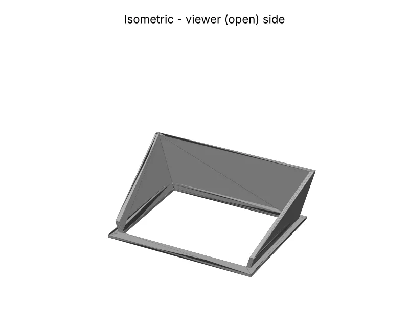
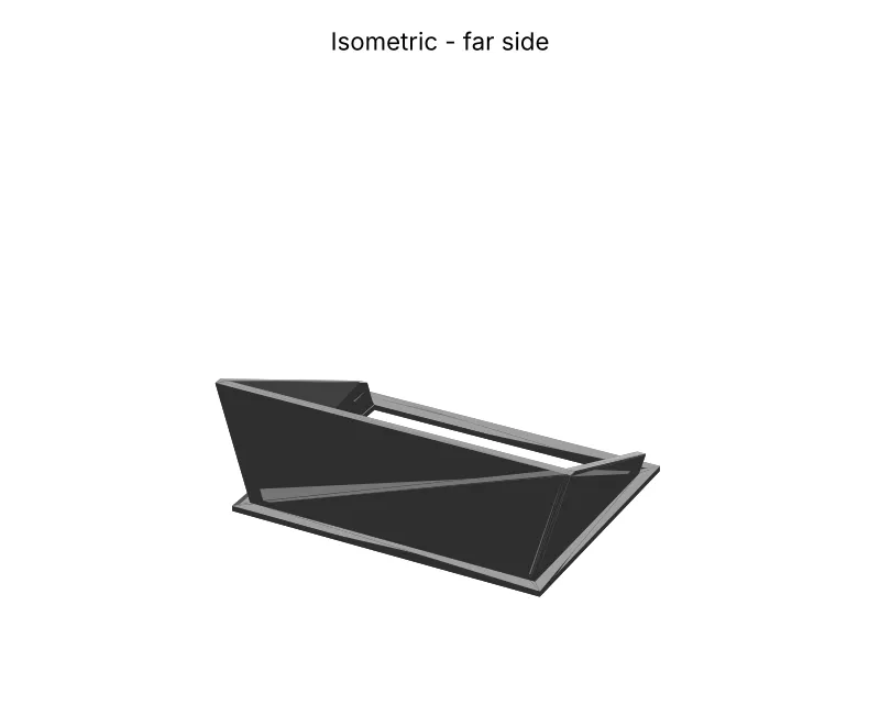
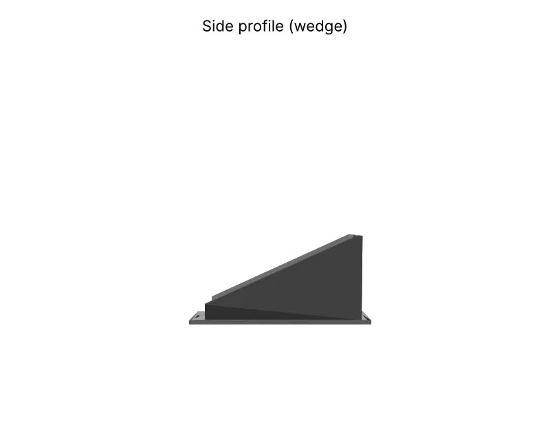
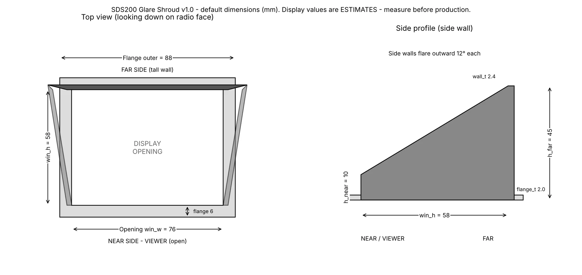
All images are CAD renders, not photos of a printed part.
Parts list
Section titled “Parts list”| Part | SKU | Price paid | Key specs | Source | Status |
|---|---|---|---|---|---|
| Glare shroud, 3D printed (sds200_glare_shroud_v1.0.stl) | TBD | TBD | ASA preferred, ABS or PETG minimum, matte black. Not PLA. | TBD | Planned |
| Fit gauge, 3D printed (sds200_fit_gauge_v1.0.stl) | TBD | TBD | 2 mm flat frame, about 88 x 70 x 2 mm, about 5 g. Print first. | TBD | Planned |
| 3M VHB tape (permanent mount) | TBD | TBD | 0.6 to 1.1 mm thick, cut to flange width | TBD | Planned |
| 3M Dual Lock low-profile or Command strips (removable mount) | TBD | TBD | Alternative to VHB | TBD | Planned |
| Isopropyl alcohol, 70 to 99%, and lint-free cloth | TBD | TBD | Surface prep | TBD | Planned |
| Black flocking paper (optional) | TBD | TBD | Self-adhesive, lines the inner walls | TBD | Planned |
Radio specs (3.5-inch color display, 1.5x DIN-E 180 x 75 mm chassis) come from the retailer listing cited in the kit: Walcott Radio, Uniden SDS200. Tape and filament guidance is general practice, not manufacturer data.
Wiring or configuration
Section titled “Wiring or configuration”There is no wiring. Configuration is the model’s parameters, edited in OpenSCAD (SOURCE/sds200_glare_shroud.scad) or passed to the Python generator.
| Parameter | Default | Range | What it does |
|---|---|---|---|
win_w |
76 mm | 40 to 120 | Opening width. Visible display width plus about 2 mm. Estimate. |
win_h |
58 mm | 30 to 100 | Opening height. Visible display height plus about 2 mm. Estimate. |
flange |
6 mm | 3 to 10 | Bonding land. Narrowest flat bezel distance minus 0.5 mm, max 8. Estimate. |
flange_t |
2.0 mm | 1.6 to 3 | Flange thickness. |
wall_t |
2.4 mm | 1.6 to 3.2 | Wall thickness. Use multiples of the nozzle width. |
h_far |
45 mm | 20 to 60 | Far-wall height. Overhead clearance minus 5 mm, max 60. |
h_near |
10 mm | 0 to 25 | Side-wall height at the viewer end. |
flare |
12° | 0 to 20 | Outward lean of the side walls. More means a wider viewing angle. |
near_lip |
0 mm | 0 to 6 | Optional lip on the open side. 0 is fully open. |
part |
shroud |
shroud or gauge |
Production part or 2 mm fit gauge. |
Python generator, for anyone without OpenSCAD:
pip install trimesh manifold3d numpypython SOURCE/generate_stl.py --win-w 78 --win-h 60 --flange 5 --out outPrint settings (from the kit’s job sheet)
Section titled “Print settings (from the kit’s job sheet)”| Setting | Value |
|---|---|
| Material | ASA (preferred), ABS, PETG (minimum). Matte black. No PLA. |
| Orientation | Flange flat on the bed, as modelled. No supports. |
| Nozzle / layer height | 0.4 mm / 0.20 mm |
| Perimeters | 6 (solid 2.4 mm walls) |
| Top / bottom layers | 5 / 5 |
| Infill | 25% gyroid |
| Brim | 5 mm for ASA/ABS |
| Seam | Aligned, far-wall outer face |
| Cooling | ASA/ABS 0 to 20%, PETG 40 to 60% |
| Enclosure | Required for ASA/ABS |
Temperatures in the kit are typical ranges (ASA 240 to 260 °C nozzle, 90 to 110 °C bed; ABS 230 to 250 / 95 to 110; PETG 230 to 250 / 70 to 85). These are general practice, not tested values. Follow your filament maker’s data sheet.
Build steps
Section titled “Build steps”- Measure the radio with calipers, to 0.5 mm: visible display width and height, the narrowest flat bezel land on all four sides, and overhead clearance in the console. Note which side faces the driver and where the strongest light comes from.
- Optional cardboard mockup. The instructions PDF has a 1:1 template (Appendix B) to cut from card and test on a bright drive before printing.
- Set the parameters from the measurements and render.
- Print the fit gauge (
part = "gauge", about 15 to 20 minutes). The display must be fully visible and the flange must sit flat without touching any button. Adjust and repeat until it fits. - Print the shroud (
part = "shroud") to the settings above. - Inspect: flange flat within about 0.3 mm, opening within ±0.3 mm of target, no layer splits at the wall-to-flange joints, no stringing inside, matte inner faces.
- Post-process: remove the brim and deburr. Optionally scuff the inner faces with 400-grit or line them with flocking paper. Do not paint the flange underside.
- Install: clean the bezel and flange with isopropyl alcohol, dry-fit with the tall wall toward the strongest light and the open side toward the driver, apply tape at least 1 mm back from the inner edge, and press for 30 seconds. VHB needs 24 hours before heat exposure.
- Check readability on a bright midday drive and tune (see the troubleshooting table in the instructions PDF).
To remove it, warm the flange with a hair dryer on low and cut the tape with fishing line or dental floss. Do not pry against the screen.
Testing and verification
Section titled “Testing and verification”| Check | Status |
|---|---|
| Both STL meshes watertight (closed, manifold) | Done. Checked by the kit’s generator on export and re-import, and re-checked independently when this page was built (0 open or non-manifold edges in either file). |
| STL bounding boxes match the drawing | Done. Shroud 99.9 x 70.0 x 45.4 mm, gauge 88.0 x 70.0 x 2.0 mm. |
| OpenSCAD source renders the same part as the STLs | Not yet. OpenSCAD was not run when the STLs were made. Render the .scad once to confirm. |
| Fit gauge printed and test-fitted on a physical SDS200 | Not yet. |
| Display-window and bezel dimensions measured on a real radio | Not yet. Defaults are estimates. |
| Shroud printed | Not yet. No print results exist for this design. |
| Installed and checked for glare and console clearance in a vehicle | Not yet. |
| Adhesive bond in heat and rough driving | Not yet. |
Safety notes
Section titled “Safety notes”- Keep the shroud and radio clear of any airbag deployment path.
- Confirm it does not interfere with the shifter, console lid, cupholders or occupants’ knees.
- Do not adjust the radio or shroud while driving. Make changes while parked.
- Deburr all edges so there are no sharp corners.
- Do not print in PLA. It can sag or warp in a hot cab.
Lessons learned
Section titled “Lessons learned”- Manufacturer specs often stop at the chassis. When the critical dimension is unpublished, design parametrically and add a cheap fit gauge, so a wrong guess costs 5 g of filament instead of a full print.
Open items
Section titled “Open items”- Measure the display window, bezel land and console clearance on the physical radio.
- Print and test-fit the gauge, then update the defaults.
- Render the OpenSCAD source once and confirm it matches the STLs.
- Print the shroud and record actual material, settings, print time and mass.
- Install, test on a bright drive, and add photos (EXIF stripped).
- Re-release as v1.1 once fit is verified.
Downloads
Section titled “Downloads”License
Section titled “License”The kit is licensed under Creative Commons Attribution-NonCommercial 4.0 International (CC BY-NC 4.0). You may print, share and remix it for non-commercial use, with credit to William A. Atkins and a note of any changes. You may not sell the files or printed parts.
Provided as-is. No warranty of fit or fitness for purpose is expressed or implied. Uniden and SDS200 are trademarks of their owner. This is an independent accessory design, not affiliated with or endorsed by Uniden.
Changelog
Section titled “Changelog”Project page published with kit downloads, licensed CC BY-NC 4.0. (build log)
Rollback: Revert the commit that added this page.
Kit released: wedge hood, bonding flange, fit gauge, parametric source and Python generator. Fit not yet verified.