
Install order and test plan
Five phases, each tested before the next one buries wires. Includes the bench power supply setup and the bench wiring for the U-Lites, the Color Flood bar, the CanTrol and the 295HFSA6 test unit.
Legal notice
Emergency lighting and siren use is regulated by state law and permits. This page documents a personal build and is not legal guidance.
Install everything in an order where each phase is tested before the next one buries wires, so a fault is always found on the bench or in the open rather than behind trim. Done means every phase below is checked off and every row of the control behavior table works in the truck.
Constraints
Section titled “Constraints”- Bench test every product on 12V before drilling or mounting.
- Make every bench connection with the supply unplugged.
- Never connect a siren speaker straight to 12V, and never run a siren tone with no speaker connected.
- The Speed Turtle EFM 3.0 can’t be bench-tested. It only works plugged into the truck’s BCM.
- The Whelen 295HFSA6 is a bench-test unit only. It is never installed on the truck.
Phase 0: before touching the truck
Section titled “Phase 0: before touching the truck”- The seller’s listing says complete set, every cable included, works as it should.
- The STE Configuration Utility is installed on the Toughbook CF-33.
- Install Whelen Command for the CanTrol WC.
- The EFM 3.0 is bought and installed.
- Buy the EFM Voltage Input Harness ($15), fuse blocks, 20A fuses and the 30A relay.
- Control head: overhead console on the Ben3DBuild mount. Check the head cable reaches the module.
- Measure runs (battery to console, battery to grille, console to visor) and pick gauges.
- Grille guard touch-up finished 23 Oct; ready to mount from about 25 Oct after a 48 hour cure.
Phase 1: bench test on 12V (no drilling)
Section titled “Phase 1: bench test on 12V (no drilling)”The CanTrol has its own step-by-step guide: the CanTrol bench test plan (Gen 3 bench test guide, 23 Oct).
- Power the module (fuse per Whelen), connect the head and mic, check each output LED for shorts.
- Connect one speaker at a time; play every tone in short bursts at low volume, people 5 ft back.
- Program the output plan over USB; save and back up.
- Slide positions 1/2/3: confirm J1 Outputs 1 to 4 and LED Outputs 3 and 4.
- Note the BooYu power-on behavior: it needs its button pressed every time (10 Oct).
- Visor bar through the Grand Control Box: dim, steady, pattern.
- Rocker bars: measure draw steady and flashing, size fuse and wire, practice sync.
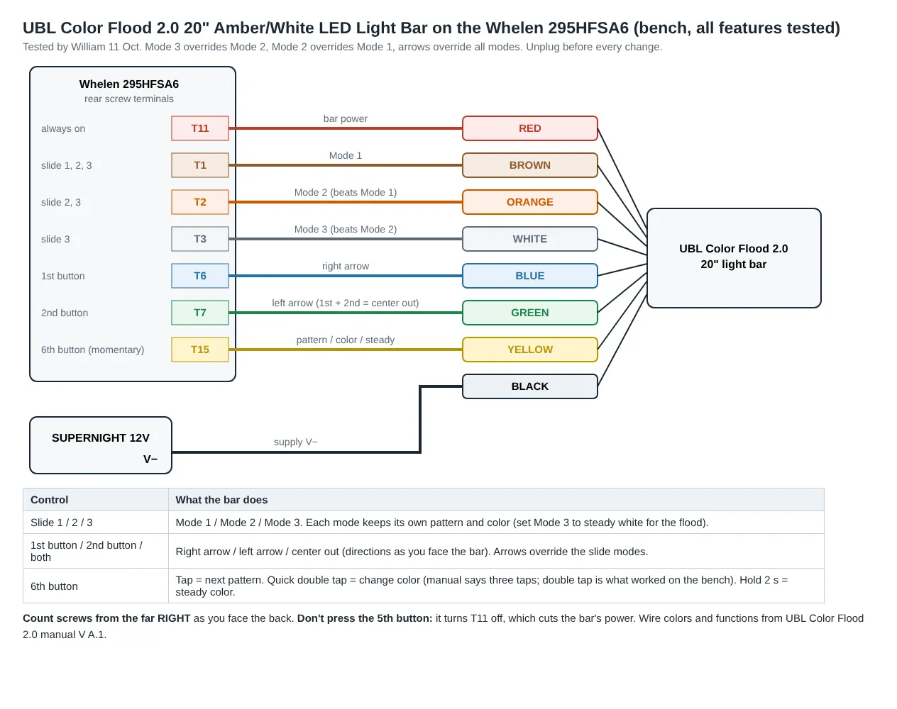
- Color Flood bar: modes, arrows and pattern wire (11 Oct). U-Lites alternate (10 Oct).
- Measure the BooYu and rocker draws while each product is on the bench.
Bench kit (arrived 10 Oct)
Section titled “Bench kit (arrived 10 Oct)”| Item | Price | Notes |
|---|---|---|
| SUPERNIGHT 12V 30A 360W power supply | $15.99 | Comes without an AC cord. Prime deal price; typically $19.99 |
| VSEER 6 ft 16 AWG 3-prong replacement power cord, open end | $8.99 | Black to L, white to N, green to ground |
| Nilight 50029R blade fuse kit with 10 in-line fuse holders | $14.39 | 120 ATC/ATO fuses 5A to 30A, 14 AWG holders, puller. Also covers wiring-day fuses |
| KAIWEETS 15A alligator clip test leads, 2 pcs, 39.6 in | $6.39 | Prime deal price; typically $7.99 |
| shuielai ceramic twist-on wire nuts, S size, 22 to 18 AWG, 25 pcs | $6.79 | Cap bare lead ends during each test |
| DOWELL wire stripper, 10 to 22 AWG, 7 in | $6.99 | My Conduct-Tite ratcheting crimper does the crimps |
Fuse for each bench test
Section titled “Fuse for each bench test”| Test | Fuse in the holder | Why |
|---|---|---|
| One U-Lite at a time | 5A (smallest in the kit) | About 0.35A each; on the truck it gets 3A |
| Color Flood 2.0 bar | 5A | 3.3A max |
| CanTrol + one speaker | 20A | Short, low-volume siren bursts only |
| 295HFSA6 + one speaker | 20A | Unit label: 8A typical with one 100W speaker, 16A with two |
Check each light’s instructions before tapping a pattern wire. On some it goes to ground, not +12V.
A. Set up the power supply (once)
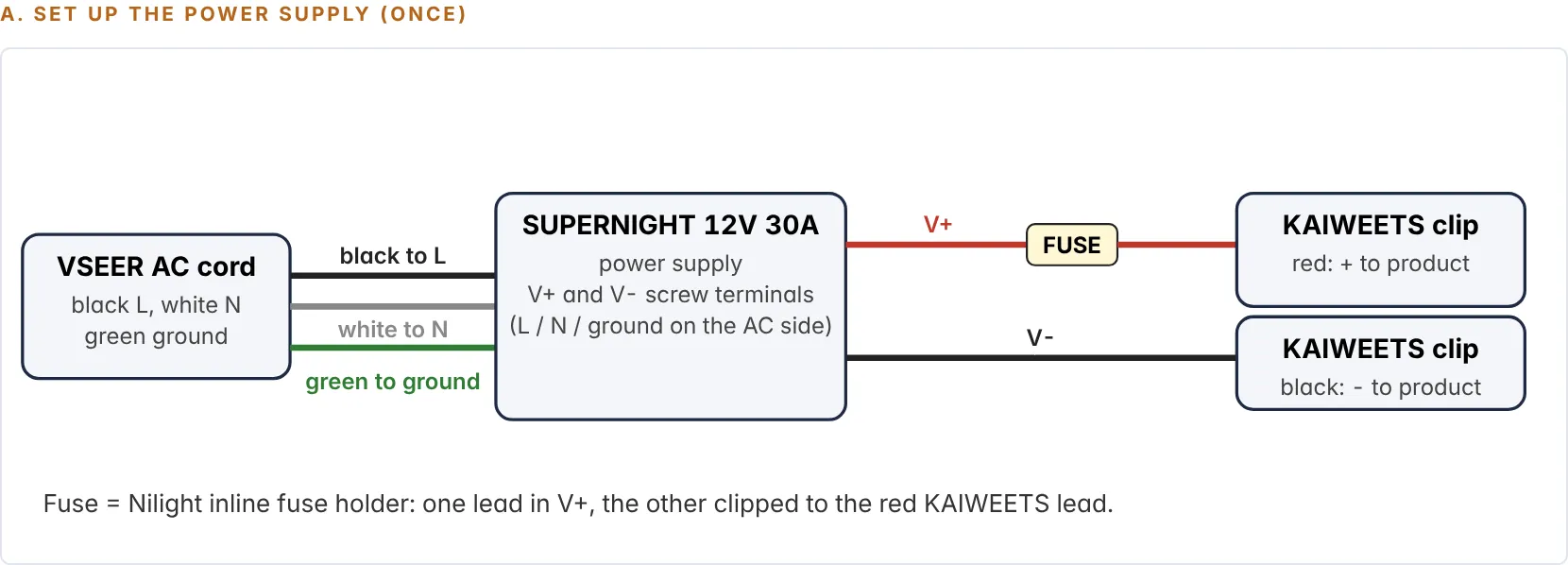
Section titled “A. Set up the power supply (once)”- Unplugged, wire the VSEER cord to the supply’s AC terminals: black to L, white to N, green to the ground symbol. Close the clear terminal cover.
- Screw one lead of a Nilight fuse holder into a V+ terminal. Screw a short black lead or clip into a V− terminal.
- Clip the red KAIWEETS lead to the fuse holder’s other end, and the black KAIWEETS lead to V−.
- Pull the fuse, plug in, and check the supply’s green LED is on. Unplug before every rewire.
B. UBL U-Lite
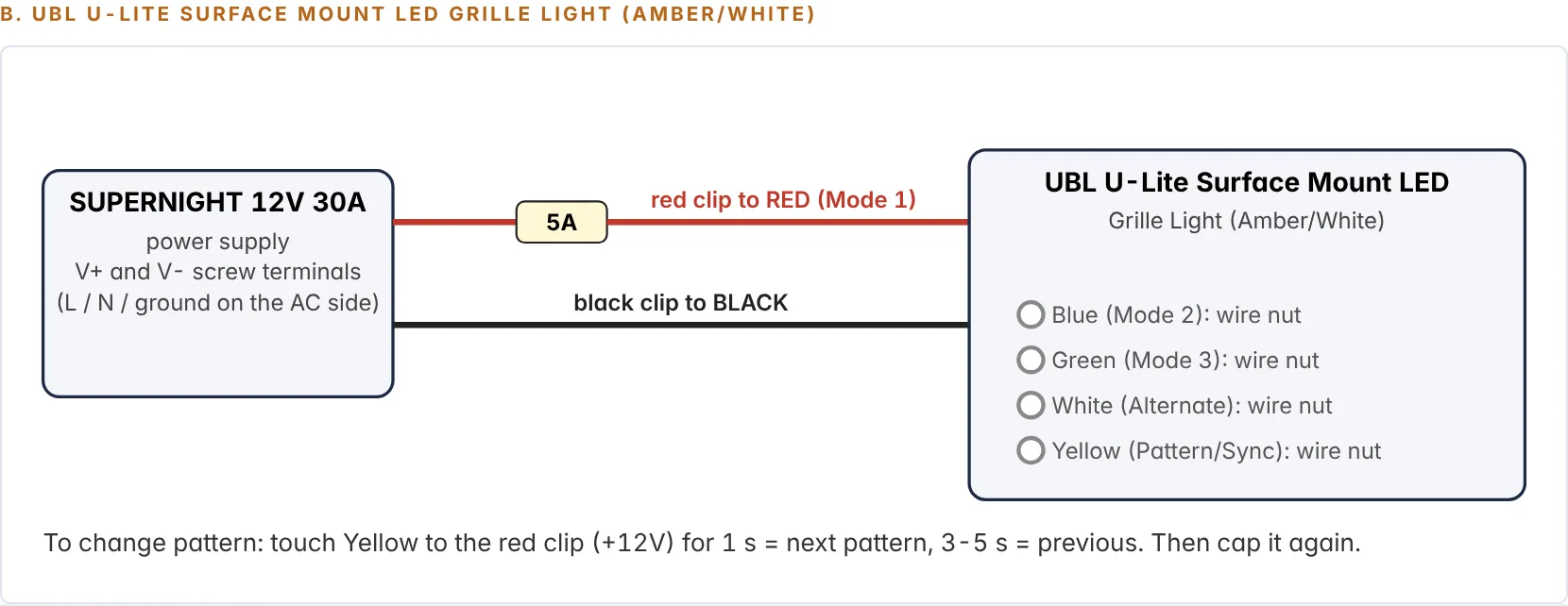
Section titled “B. UBL U-Lite”Fuse 5A. Red clip to red (Mode 1), black clip to black. Wire-nut blue, green, white and yellow. Plug in: it flashes. Yellow to +12V for 1 s steps patterns; 3 to 5 s steps back. Optionally check Modes 2 and 3 on blue and green, then both lights together with yellows joined and one white on +. Full steps on the U-Lite page.
C. UBL Color Flood 2.0 bar
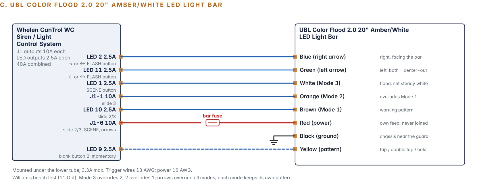
Section titled “C. UBL Color Flood 2.0 bar”Fuse 5A. Red alone on the red clip, black on the black clip, every other wire capped separately. Red alone does nothing. Touch brown, orange, then white to +12V for Modes 1 to 3; blue and green for the arrows; yellow for pattern, color and steady. Never join red to a mode wire. Full steps and results on the Color Flood page.
D. Whelen CanTrol WC
Section titled “D. Whelen CanTrol WC”- Fuse 20A. Twist both red power wires together into the fuse holder’s lead (no clip). Put both black ground wires on V−. With one red left off, part of the unit can stay dead and look like a fault.
- Plug the control head cable into the module, and the mic into the module’s 1/4 in mic jack.
- Speaker: the module’s orange speaker wire to the speaker’s white (+), brown to its black (−). One speaker only on the bench.
- Plug in. Check the head lights up and each output’s indicator LED shows no short.
- Run each siren tone in short, low-volume bursts. Try the PA mic.
- Optional output check: one U-Lite’s red on an output (for example J1-4), black on V−. The light comes on when that output is selected on the head.
- Connect the Toughbook by USB and confirm Whelen Command sees the unit. Save the existing program before changing it.
Ignition sense: also put the red/white ignition wire (J17-7) on V+ through the fuse holder. Without it the system stays off.
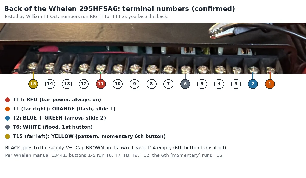
E. Whelen 295HFSA6 (bench unit only)
Section titled “E. Whelen 295HFSA6 (bench unit only)”- Fuse 20A. Both heavy red leads twisted together into the fuse holder (mine have no tags), black to V−.
- Speaker: yellow to the speaker’s + (white), brown to its − (black). Wire-nut orange (the second-speaker output).
- Wire-nut the optional wires: blue (radio), violet (siren shut-down), white and grey (horn relay).
- Optional: white/yellow to +12V turns on the panel backlight.
- Turn the power switch on. Set the rotary knob to RAD, press and release MAN to run SI-TEST: the diagnostic light stays steady about 1.5 s if there’s no fault. A single flash on the speaker LED means a speaker short.
- Try the siren tones in short, low-volume bursts.
- Optional output check: one U-Lite’s red to terminal 1, black to V−. With factory settings it comes on in slide position 1 (position 2: terminals 1 and 2; position 3: terminals 1 to 5).
Whelen 295HFSA6 (bench unit)
- Label
- 12.8 VDC ±20%; 8A typical at 100W, 16A at 200W (both at 15 VDC); 11 Ω speaker; built 10/07
- Part number
- 01-0864480-000
- Onboard fuse
- 20A blade
- Terminals
- 1 and 2: 20A. 3 to 5: 20A combined. 6 to 9, 11, 12, 14, 15: 10A each (11 and 14 always on)
- Default slide
- Position 1 = terminal 1; 2 = terminals 1–2; 3 = terminals 1–5
Source: 295HFSA6 installation manual excerpts on ManualsLib (pp. 4, 5, 7), and my photos of the unit label, 8 Oct 2026
Phase 1b: mock-up on the guard
Section titled “Phase 1b: mock-up on the guard”UBL parts and JOUGU ties arrived 10 October. Fit everything to the guard on the ground before the permanent mounting, hand-tight only, no thread locker, tape in place of the steel ties, and protect the new paint.
- U-Lite box screws fit the housing snugly (10 Oct). Still to check: each light centered over a plate hole.
- Speakers: at least two threads past the nut, or note a longer bolt in the same thread.
- A JOUGU tie passes through the gap behind the lower tube with plenty of room (10 Oct). Still to check: bracket tips hidden, tie fits the bracket slot.
- Photograph each spot before the permanent mount.
Phase 2: truck power and mounting
Section titled “Phase 2: truck power and mounting”- Battery negative off. Fuse blocks within 2 ft of the battery, fuses out.
- Amplifier on its floor plate under the driver-side rear seat, with air above the fins. Head on its mount, clear of airbags and the driver’s knee.
- Power leads through an existing factory firewall grommet: passenger side behind the glove box, or driver side behind the pedals.
- A shop mounts the grille guard, because the splash shield needs trimming at the tow hook brackets (13 Oct). One quote: 2 h at $150/h = $300, less if faster. Then the speakers, Color Flood bar and U-Lites per the grille guard page; touch up any marks.
- Q-RVF15 bracket and visor bar, cable along the headliner and A-pillar (18 Oct).
- BooYu traffic advisor and controller.
- Rocker bars low on the sills; relay and fuses; LED Output 3 to the coil.
- Putco Work Blade on the rear bumper, rear plate bracket and Z-6 heads, CC5K1 at the OBD-II port.
Phase 3: Speed Turtle EFM 3.0 (front passenger footwell)
Section titled “Phase 3: Speed Turtle EFM 3.0 (front passenger footwell)”- Installed inline at BCM J3 and J7 (8 Oct).
- Switch it to voltage input: fit the Voltage Input Harness.
- White to the LED Output 4 wire, green to the LED Output 5 wire.
- Battery on; program with the STE utility; test white, green, both and double-pull; confirm brake, turn and reverse still work.
Phase 4: final wiring and full test
Section titled “Phase 4: final wiring and full test”- Crimped connectors, loom, grommets; away from heat, fans and moving parts.
- Insert fuses one at a time.
- Run every row of the control behavior table.
- Low-speed private drive: chafing, factory lights normal, light bar ties and grille hardware tight.
- Re-check connections and mounting bolts after the first week.
- Photograph every fuse location and the CanTrol settings before closing up.
Sources
Section titled “Sources”- Whelen CanTrol WC guide 14580G
- UBL U-Lite manual v C.1, UBL Color Flood 2.0 instructions v A.1
- Whelen 295HFSA6 installation manual excerpts on ManualsLib, pp. 4, 5 and 7
- F-150 project document, revision 10, section 10, and the bench test wiring guide
Changelog
Section titled “Changelog”Page published from the 23 October project files.
Rollback: Revert the commit that rebuilt the F-150 section.