
UBL Color Flood 2.0 grille light bar
20" amber/white warning and white flood bar under the grille guard's lower tube, with seven CanTrol outputs for power, three modes, two arrows and pattern.
Legal notice
Emergency lighting and siren use is regulated by state law and permits. This page documents a personal build and is not legal guidance.
One light bar on the front of the truck that does three jobs: an amber/white warning pattern, a steady white flood for scene and work lighting, and directional arrows. Every function is run from the Whelen CanTrol WC control head, with no separate switch box. Done means every wire is landed on its planned CanTrol output, each function works from its button in the truck, and the measured draw is recorded here.
Constraints
Section titled “Constraints”- Location: under the lower horizontal tube of the Steelcraft HD Grille Guard (50-1420C), above the license plate. No drilling, welding or bending of the guard.
- Controller: every function comes from the CanTrol WC. The bar makes its own patterns, so each CanTrol output feeding it is set to steady on/off.
- Grounds: never to the battery negative post on this truck. The 2015+ F-150 measures charge with a sensor on the negative lead, and Ford says all negative current must pass through it. The body is aluminum, so no grounds on sheet metal either.
- Airbags: UBL warns against mounting or routing in an airbag deployment area. This bar and its wiring are entirely outside the cab, forward of the grille.
Architecture
Section titled “Architecture”The bar has eight leads. Red is its power and needs its own feed. Brown, orange and white select one of three modes, blue and green run the arrows, and yellow steps the pattern and color. Each mode remembers its own pattern and color.
Priority, confirmed on the bench: Mode 3 overrides Mode 2, Mode 2 overrides Mode 1, and the arrows override all three modes.
Whelen CanTrol WC (under driver-side rear seat) J1-6 (10A, BLU lead) ── bar in-line fuse ── RED power slide 2/3, SCENE, ←, →, ↔ FLASH J4-14 (LED 10, BLU) ─────────────────────── BROWN Mode 1 warning slide 2/3 J1-1 (10A, BRN lead) ─────────────────────── ORANGE Mode 2 warning slide 3 J4-3 (LED 1, BRN) ─────────────────────── WHITE Mode 3 flood SCENE (latched) J4-4 (LED 2, RED) ─────────────────────── BLUE right arrow → and ↔ FLASH (latched) J4-15 (LED 11, check) ─────────────────────── GREEN left arrow ← and ↔ FLASH (latched) J4-13 (LED 9, GRN) ─────────────────────── YELLOW pattern/color blank button 2 (momentary) Ground run ─────────────────────────────────── BLACK to steel frame rail side (or Ford Q-231 point)Red alone does nothing. The bar lights only with red plus a mode or arrow wire, which is why J1-6 is on in every state that uses the bar. The full output map is on the CanTrol output plan.
UBL Color Flood 2.0, 20 in, amber/white
- SKU
- UBL-CF-2120
- Wires
- 8: red, brown, orange, white, blue, green, yellow, black
- Modes
- 3, each with its own remembered pattern and color
- Arrows
- Blue = right, green = left, both = center-out
- Fuse
- Built-in removable in-line fuse on red
- Max draw
- 3.3A (108W), not yet measured
- Voltage
- 10–30V
- Size
- 20 x 1.625 x 3 in
Source: UBL Color Flood 2.0 instructions, SKU UBL-CF-2120, version A.1 (wires, modes, arrows, fuse). Draw, voltage and size: my grille guard install proposal, 5 Oct 2026 (not a UBL document)
Unverified
The instruction sheet does not list draw, voltage, size, IP rating or the in-line fuse’s amp rating. Those three come from my own install proposal, not from a UBL document. The IP rating and the in-line fuse’s rating are still unknown. The project parts list allots a 5A blade fuse for this feed (wire C1), matching the 5A fuse used on the bench, and replaces an early plan of 10A on 16 AWG for a 72W bar. The UBL product page could not be reached to check them, so no product link is given yet.
Parts list
Section titled “Parts list”| Part | SKU | Price | Key specs | Source | Status |
|---|---|---|---|---|---|
| UBL Color Flood 2.0 20" Amber/White LED Light Bar (amber/white with white flood) | UBL-CF-2120 | $152.00 | 3.3A max (unverified), 8-wire, in-line fuse | TBD | Bench-tested |
| UBL adjustable L-brackets (included with the bar) | TBD | TBD | Bolt to the bar's rear slide-in channel | TBD | In progress |
| Black rubber anti-vibration pads, about 2" square (x2) | TBD | TBD | One under each bracket | TBD | In progress |
| Black epoxy-coated stainless cable ties (x4) | TBD | TBD | Two per bracket around the 1.91" OD tube | TBD | In progress |
| Blue thread locker | TBD | TBD | Bracket short leg to bar channel | TBD | In progress |
| 16 AWG wire (power) and 18 AWG wire (triggers), loom, grommets | TBD | TBD | Run from the guard to the CanTrol module | TBD | Planned |
Wiring
Section titled “Wiring”Gauges come from the project document’s fuse and wire table: 16 AWG for power, 18 AWG for trigger wires. CanTrol pins and lead colors come from Whelen guide 14580G. Bar wire colors come from UBL’s instructions and match the label on my bar.
| Wire | Color | Function | Source output | Draw | Fuse | Gauge | Relay pin | Termination | Ground |
|---|---|---|---|---|---|---|---|---|---|
| C1 | Red | Power. Own feed only, never joined to a mode wire | J1-6 (10A, BLU lead), positive-switched | 3.3A max (unverified) | Bar in-line fuse (rating not read yet; the parts list allots a 5A blade for this feed) + CanTrol internal | 16 AWG | — | Bench: wire nut. Truck: TBD | TBD |
| C2 | Blue | Right arrow, as seen facing the bar | J4-4 (LED 2, RED lead) | Signal only, not measured | CanTrol J4 group 20A | 18 AWG | — | Bench: wire nut. Truck: TBD | TBD |
| C3 | White | Mode 3, set to steady white flood. Overrides Modes 1 and 2 | J4-3 (LED 1, BRN lead) | Signal only, not measured | CanTrol J4 group 20A | 18 AWG | — | Bench: wire nut. Truck: TBD | TBD |
| C4 | Yellow | Pattern: tap = next, double tap = color, 2 s hold = steady | J4-13 (LED 9, GRN lead), momentary | Signal only, not measured | CanTrol J4 group 20A | 18 AWG | — | Bench: wire nut. Truck: TBD | TBD |
| C5 | Black | Ground | — | Return for C1 | — | 16 AWG | — | Ring terminal, star washer, sealed | Side of a steel frame rail, or the Ford SVE Q-231 ground point. Never battery negative |
| C6 | Brown | Mode 1, warning pattern | J4-14 (LED 10, BLU lead) | Signal only, not measured | CanTrol J4 group 20A | 18 AWG | — | Bench: wire nut. Truck: TBD | TBD |
| C7 | Orange | Mode 2, warning pattern. Overrides Mode 1 | J1-1 (10A, BRN lead) | Signal only, not measured | CanTrol internal | 18 AWG | — | Bench: wire nut. Truck: TBD | TBD |
| C8 | Green | Left arrow, as seen facing the bar. Blue + green = center-out | J4-15 (LED 11, lead color CHECK) | Signal only, not measured | CanTrol J4 group 20A | 18 AWG | — | Bench: wire nut. Truck: TBD | TBD |
No relay is used. Every bar wire lands directly on a CanTrol output.
Unverified: lead color on J4-15
Whelen guide 14580G shows LED Output 11 (J4-15) as violet on page 7 and orange on page 10. Identify that lead by pin number and with a meter, not by color.
Unverified: J1-6 switching polarity
J1 Outputs 5 to 8 can switch positive or ground, set by which fuse slot each output’s fuse sits in (guide 14580G, p.8). This is a used module, so a previous owner may have left J1-6 in the ground-switching slot. Check it before connecting the bar: the module’s indicator shows green for positive switching and amber for ground switching.
CanTrol programming
Section titled “CanTrol programming”Set in Whelen Command, per the project’s wiring research. These settings are inferred from how the bar works and have not been programmed yet.
| Output | Action | Switch type | Notes |
|---|---|---|---|
| J1-6, J1-1, LED 10 | Turn On, steady | Follows slide position | No flash pattern, Low Power disabled |
| LED 1 (SCENE) | Turn On, steady | Press On / Press Off | Latched |
| LED 2, LED 11 (arrows) | Turn On, steady | Press On / Press Off | ↔ FLASH turns on both |
| LED 9 (blank button 2) | Turn On, steady | Press On / Release Off | Must be momentary. If yellow is held on, the bar reads a 2 s hold and goes to steady color |
A flash pattern or Low Power on any of these outputs would switch the bar’s inputs on and off, so the bar would flicker or restart its pattern.
Build steps
Section titled “Build steps”- Bench test the bar alone on a 12V supply with a 5A fuse in the holder. Red alone on the red clip, each other wire capped separately and touched to +12V one at a time. Done 2026-10-11.
- Set each mode’s pattern and color with the yellow wire. Set Mode 3 to steady white for the flood.
- Bench test the bar on the CanTrol, wired exactly as in the table above (Gen 3 bench guide, Stage 4).
- Bolt the included L-brackets to the bar’s rear slide-in channel, about 6” either side of center, with blue thread locker on the short leg.
- Hang the bar under the lower tube. The long slotted leg lies on top of the bar, curve turned inward, on a rubber pad. Two coated stainless cable ties per bracket go around the tube and through the bracket slot, buckles to the back. Touch up the cut ends.
- Check that the bar clears the license plate.
- Loom the eight leads along the guard and through the grille, with a grommet at every metal pass-through, then run them to the CanTrol module.
- Land the ground on the side of a steel frame rail (or the Q-231 point): bare metal, star washer, sealed afterward.
- Program the outputs in Whelen Command and save the program file.
- Re-check the cable ties after the first few drives.
Testing and verification
Section titled “Testing and verification”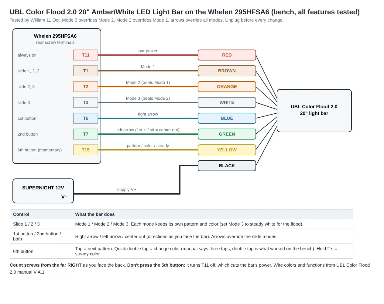
Bench-tested on 2026-10-11 (on a 12V supply and a Whelen 295HFSA6 test amp, not the CanTrol):
- All eight wire colors match UBL’s instructions and the label on the bar.
- Red alone does nothing. The bar needs red plus a mode or arrow wire.
- Brown, orange and white each run their own pattern. With two on, the higher mode shows.
- Blue gives the right arrow and green the left arrow, as seen facing the bar. Both together give center-out. The arrows override all three modes.
- Yellow: a tap steps to the next pattern, a quick double tap switches amber/white, and a 2 s hold gives steady color. Each mode keeps its own setting.
Not yet tested:
- Driving the bar from the CanTrol (Gen 3 bench guide Stage 4, tests 4.1 to 4.11).
- Whether each mode’s memory survives a power-off of at least 10 seconds.
- Measured current on the red wire in Mode 2 and in the white flood.
- Anything in the truck.
Safety notes
Section titled “Safety notes”- Fuse every feed. The bar’s in-line fuse stays in circuit, and if it is ever removed it is replaced with the same or a similar fuse, per UBL.
- Never join red to a mode wire.
- UBL’s sheet says to ground to the battery negative post. On this truck Ford’s rule wins: ground to a steel frame rail side or the Q-231 point, never battery negative and never aluminum sheet metal.
- Grommet every metal pass-through and loom the whole run through the grille.
- UBL notes these are high-intensity lights. Don’t look straight into the bar during bench tests, and don’t operate it in hazardous driving conditions.
- Check every function visually before the truck goes back into service.
Lessons learned
Section titled “Lessons learned”- The red lead is power only. Red alone does nothing, and joining it to a mode wire defeats the mode logic, so it needs its own output.
- On my bar, a quick double tap on yellow changes color. UBL’s sheet says three taps.
- Because the bar handles its own priority (Mode 3 over 2 over 1, arrows over all), the CanTrol only needs simple steady outputs. No CanTrol flash patterns are needed for this bar.
Open items
Section titled “Open items”- Measure the draw on the red wire, and record the in-line fuse’s amp rating (5A planned for C1).
- Confirm the bar’s IP rating with UBL.
- Confirm J1-6 is in the positive-switching fuse slot.
- Identify the J4-15 lead by pin and meter.
- Find the ground point on the frame rail side, or match the Q-231 point to Ford’s bulletin photo.
- Decide the truck terminations (crimp butt splice with adhesive heat shrink, or a sealed connector at the guard so it can come off).
- Optional: move orange (Mode 2) from J1-1 to a spare LED output to keep a 10A output free.
- The all-lights five-modes plan may re-store this bar’s mode memories. It needs no new wires.
- Add the manufacturer product link.
Changelog
Section titled “Changelog”Wire IDs renamed from CF1–CF8 to C1–C8 to match the project document and the power and wiring page. Colors and functions unchanged.
Rollback: Revert the commit that made this change.
Added the 5A fuse allotted for the power feed in the project parts list, and the 295HFSA6 all-features bench diagram. Moved in the sidebar to sit with the other grille guard products.
Rollback: Revert the commit that rebuilt the F-150 section.
Component page published with the wire-by-wire plan, bench results and open items. Ground changed from "chassis near the guard" to a steel frame rail side or the Ford Q-231 point, per the 21 Oct wiring research. (build log)
Rollback: Revert the commit that added this page.