
Putco 60-inch Work Blade
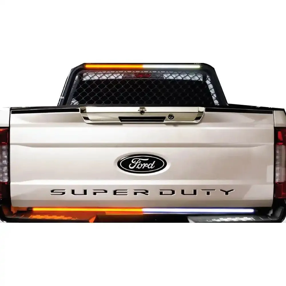
Amber/white 60" Work Blade on top of the rear bumper under the tailgate. CanTrol J1-5 powers it on an amber pattern; the Putco remote's A button gives white override and B steps patterns.
Legal notice
Emergency lighting and siren use is regulated by state law and permits. This page documents a personal build and is not legal guidance.
Rear amber warning lighting across the full width of the truck, plus a steady white work light for loading while stopped. Done means the bar is stuck to the bumper, powered from J1-5, the remote works from the cab and at the tailgate, and the draws are recorded.
Constraints
Section titled “Constraints”- No drilling. The bar sticks on with 3M tape on Putco’s plastic brackets.
- Outside the truck. It mounts low, along the top of the rear bumper under the closed tailgate. The BooYu stays in the rear window.
- White only when stopped. Remote button A is white override for loading or working behind the truck.
- Positive switching. J1-5 can switch positive or ground, set by which fuse slot its fuse sits in (guide 14580G p.8). It must be in the positive-switching slot.
- Draw not published. Neither Putco document gives the bar’s draw or the remote box’s standby draw.
Putco Amber & White Work Blade, 60 in, with Wireless Remote Kit V3
- Bought
- 18 Oct 2026, $253.37 shipped, remote included
- Bar kit
- LED bar, black plastic brackets, 3M tape strips and promoter, Scotchlok connectors, rocker switch (not used)
- Remote box
- 2.1 x 1.5 x 1 in, IP65K, 10–30V DC, 25A max, 433 MHz, 50 ft open-air range, 1/4 in male spades
- Fob
- 27A 12V alkaline battery, sliding cover, blue LED. 1-year warranty
- Draw
- Not in either document. Measure
- Manuals
- Putco Blade install form 93009I; Four-Button Wireless Remote P/N 93020 Rev B
Source: Putco forms 93009I and 93020 Rev B
How the CanTrol and the remote share the bar
Section titled “How the CanTrol and the remote share the bar”Putco’s remote wiring (93020, p.7) puts remote blue on bar blue (A = power on/off) and remote yellow on bar orange (B = change pattern). When a cab switch also powers the bar, Putco says to move remote blue to the bar’s white wire, so A becomes white override. That’s this build: the CanTrol is the cab switch on blue, so the remote never feeds the same wire as a CanTrol output.
| Control | What it does |
|---|---|
| CanTrol slide 2 and 3 | Powers the bar (blue) on its amber-only pattern |
| Remote A | Latches white override on and off: steady white to the rear while stopped. Press A first to wake the remote; it lights the fob’s blue LED |
| Remote B | Steps to the next pattern (a 250 ms pulse to ground on orange), so orange doesn’t need to be tapped by hand |
| Remote C and D | Not used on the Work Blade. Their wires are capped |
Wire colors and functions
Section titled “Wire colors and functions”| Wire | Function | Connects to | Notes |
|---|---|---|---|
| Bar blue | 12V+ power | J1-5 (10A), slide 2 and 3 | Replaces the supplied rocker switch |
| Bar white | White override | Remote blue (button A) | Check on the bench whether white works with blue off |
| Bar orange | Next pattern when grounded | Remote yellow (button B) | Stays connected to the remote |
| Bar red | Auxiliary, troubleshooting only | Capped | |
| Bar black | Ground | Frame rail at the rear | |
| Remote red | Constant 12V+ | Accessory fuse block, 5A | Putco gives no fuse size; 5A is my choice since the remote only switches signal wires (inferred) |
| Remote black | Constant ground | Frame rail at the rear, with the bar’s black | |
| Remote green, grey | Buttons D and C, momentary to ground | Capped |
Wiring
Section titled “Wiring”| Wire | Color | Function | Source output | Draw | Fuse | Gauge | Relay pin | Termination | Ground |
|---|---|---|---|---|---|---|---|---|---|
| T1 | Bar blue | +12V, amber-only pattern | J1-5 (10A, green lead), slide 2/3, positive slot | Not published; measure | CanTrol J1 output fuse (10A) | 14 AWG | — | Deutsch DT 4-pin at the rear | TBD |
| T2 | Remote red | Constant +12V | Accessory fuse block (tag A) | Standby not published; measure | 5A ATC (inferred) | 18 AWG | — | 1/4 in female heat-shrink spade | TBD |
| T3 | Remote blue to bar white | Button A, white override, stopped only | Remote box | Signal | — | 18 AWG | — | Spade at the box, DT at the bar | TBD |
| T4 | Remote yellow to bar orange | Button B, next pattern (250 ms to ground) | Remote box | Signal | — | 18 AWG | — | Spade at the box, DT at the bar | TBD |
| T5 | Remote green and grey | Buttons C and D, not used | — | — | — | — | — | Heat-shrink end caps | TBD |
| T6 | Bar red | Auxiliary, not used | — | — | — | — | — | Capped at the bar | TBD |
| T7 | Bar black + remote black | Ground | — | Return | — | 14 AWG | — | One sealed ring terminal, star washer | Clean bare-metal point on the steel frame rail near the bumper. Never battery negative |
| T8 | T1 + T2 | Cab to rear bumper run | Amplifier area and fuse block | — | — | 3/8 in black split loom | — | Existing floor grommet, along the frame rail | TBD |
| T9 | Blue, white, orange, black | Rear unplug point | — | — | — | — | — | Deutsch DT 4-pin, so the bar unplugs | TBD |
Routing (general knowledge): from the amplifier under the rear seat and the accessory fuse block, out through an existing body grommet in the rear cab floor (no new holes), along the frame rail in loom, clear of the exhaust and the spare tire and its cable, then up behind the bumper. Mount the remote box on the frame or a bumper bracket near the bar, leads pointing down, out of direct spray, with zip ties or its two mounting holes. The truck’s steel can shorten the 50 ft range, so test the fob before fixing the box. If range is poor, move the box higher or inside the bed rail.
Mounting
Section titled “Mounting”Where (general knowledge): along the top of the rear bumper, under the closed tailgate, as in Putco’s photo. On the bumper the wires don’t flex across the tailgate hinge. Before pressing it on, check the tailgate opens and closes clear, and that the bar doesn’t cover the spare tire crank access, backup camera, plate lamps or hitch. The plastic brackets can space the bar off anything in the way.
How (Putco manual): surface clean, dry and 60°F (15°C) or warmer. Tape on the back of the plastic brackets, prepped with the promoter. Isopropyl alcohol (90% or stronger) on the truck surface. Clip one bracket near each end of the bar, then stick it in place. The tape is very hard to remove, so set the position before pressing it on.
Tools from Putco’s list: 90% or stronger isopropyl alcohol, a clean towel, pliers and electrical tape.
Color combinations
Section titled “Color combinations”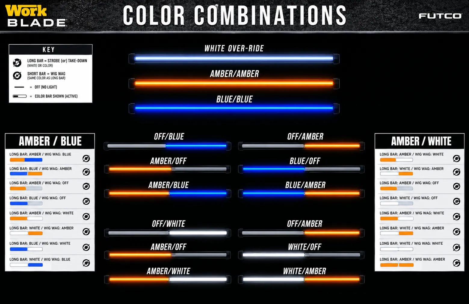
Bench test on 12V before mounting
Section titled “Bench test on 12V before mounting”- SUPERNIGHT 12V supply. 10A fuse in a Nilight in-line holder on the bar’s blue lead, 5A on the remote’s red lead. Both blacks to supply −. Bar red capped.
- Remote standby: meter in series on the remote’s red, nothing pressed. Record the draw, since it runs on constant power.
- Bar draw: meter in series on blue, blue to +. Record the reading.
- Remote: remote blue to bar white, remote yellow to bar orange. Press A (fob LED lights), then B to step patterns. Stop on an amber-only pattern (amber/amber on Putco’s chart) and record which one.
- White override: with blue on, press A for white. Then with blue off, press A again. Record whether white needs blue, and its draw.
- Power off and on: confirm the bar keeps the chosen pattern.
- Write the draws and the pattern on this page.
Open item
The remote is on constant power. Ford’s guideline for total key-off draw is 28 mA or less (see the controller page). The remote’s standby draw needs measuring against that before it’s left connected full time.
Changes to the install config
Section titled “Changes to the install config”| Row | Before | Now |
|---|---|---|
| J1-5 (10A) | Spare | Work Blade blue (+12V), slide 2/3 |
| J1-7 (10A) | Spare | Still spare: the remote handles white override |
| Accessory fuse block | — | One 5A circuit for the remote box |
| BooYu | J1-3 | Unchanged. The Work Blade mounts separately, outside under the tailgate |
| Parts | — | Nothing extra to buy: wire, loom, ring terminal, star washer, end caps, spade terminals and the DT kit are already on the master list |
Five-modes option
Section titled “Five-modes option”In the five-modes plan (decision D), the bar’s white wire could move to a CanTrol LED output so steady white and white flash are one press. The remote’s A button and the CanTrol can’t both feed the white wire without isolation, so either A goes unused, or two 3A diodes let both work (general knowledge).
| Part | SKU | Price | Key specs | Source | Status |
|---|---|---|---|---|---|
| Putco Amber & White Work Blade LED Lights, 60" Long, Amber and White Strobe, with Putco Wireless Remote Kit V3 | TBD | $253.37 shipped | Tailgate bar, 3M tape mount | TBD | In progress |
| 5A blade fuse and in-line holder | TBD | TBD | T2, from the Nilight kit | TBD | Planned |
| Deutsch DT 4-pin connector | TBD | TBD | T9, from the DT kit | TBD | Planned |
| 1/4 in female heat-shrink spade terminals | TBD | TBD | Remote box | TBD | Planned |
Open items
Section titled “Open items”- Measure the bar’s draw and the remote’s standby draw.
- Record the amber-only pattern chosen.
- Check whether white override works with blue off.
- Confirm J1-5 is in the positive-switching fuse slot.
- Test the fob range before fixing the remote box.
Sources
Section titled “Sources”- Putco Blade LED Light Bar Installation Instructions, form 93009I
- Putco Four-Button Wireless Remote Instructions, P/N 93020 Rev B
- Putco color combination chart and product photo
- Whelen CanTrol WC guide 14580G, p.8 (positive or ground switching on J1 Outputs 5 to 8)
- F-150 project document, revision 10, sections 8.3 and 9.3 (T1 to T9)
Changelog
Section titled “Changelog”Replaced the color combination chart with a sharper copy (1559 x 1009, was 853 x 552).
Rollback: Revert the commit that replaced the chart.
Page published from the 23 October project files.
Rollback: Revert the commit that rebuilt the F-150 section.