
UBL U-Lite grille lights
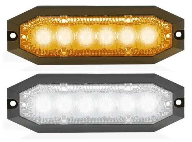
Two amber/white U-Lites in the upper punch plate corners, fed from J1-4 through a 3A fuse, yellows joined for sync and one white lead used so they alternate.
Legal notice
Emergency lighting and siren use is regulated by state law and permits. This page documents a personal build and is not legal guidance.
Two small amber/white warning lights high on the grille guard, flashing in sync and alternating left and right, run from one CanTrol output. Done means both are mounted on the punch plate with machine screws, wired through a 3A fuse within 12 in of the output, and working from the slide switch in the truck.
Constraints
Section titled “Constraints”- Location: upper left and upper right corners of the punch plate (decided 6 Oct; the first proposal had them in the lower corners).
- No drilling. Each light is centered over an existing punch plate hole, so its leads run straight back through it.
- Fuse: UBL calls for a 3A fuse within 12 in of the power source.
- Ground: frame rail side or the Ford Q-231 point, never the battery negative post.
UBL U-Lite Surface Mount LED Grille Light, amber/white
- SKU
- UBL-UL2-SM
- Size
- 4.40 x 1.25 x 0.40 in, mounting tab at each end
- LEDs
- 6
- Voltage
- 12V
- Draw
- 350 mA max each, 0.70A for the pair
- Leads
- About 6 in, 18 AWG
- Patterns
- 40, including Steady 1/2 and Brake 1/2
- Fuse (UBL)
- 3A within 12 in of the source
- Paid
- $85.50 for two (listing $44.99 single color, $54.99 dual)
Source: UBL U-Lite manual, SKU UBL-UL2-SM, version C.1. Size and draw: my 5 Oct install proposal
Wire functions
Section titled “Wire functions”| Lead | Function (UBL manual) | Plan |
|---|---|---|
| Red | Mode 1: powers the light in Mode 1 | Both reds to J1-4 through the 3A fuse |
| Blue | Mode 2 | Capped, each separately |
| Green | Mode 3 | Capped, each separately |
| Yellow | Pattern / Sync | The two yellows joined for sync. A brief +12V steps the pattern |
| White | Alternate | Left light’s white on J1-4 after the fuse, so the pair alternates. Right light’s white capped |
| Black | Ground | Both to a frame rail ground |
Patterns: +12V on yellow for 1 second steps to the next of 40 patterns. 3 to 5 seconds steps back.
Wiring
Section titled “Wiring”| Wire | Color | Function | Source output | Draw | Fuse | Gauge | Relay pin | Termination | Ground |
|---|---|---|---|---|---|---|---|---|---|
| U1 | Red (both lights) | Mode 1 power, spliced | J1-4 (10A, yellow lead), slide 2/3 | 0.70A max total (UBL 350 mA each) | 3A in-line within 12 in of J1-4, plus CanTrol internal | 16 AWG run, 18 AWG leads | — | Solder-seal splice, Deutsch DT at the guard | TBD |
| U2 | White (left light) | Alternate, makes the pair alternate | J1-4 after the 3A fuse | Signal | Shares U1 fuse | 18 AWG | — | Solder-seal splice | TBD |
| U3 | Yellow to yellow | Pattern / sync between the lights | — | — | — | 18 AWG | — | Sealed splice | TBD |
| U4 | Black (both) | Ground | — | Return | — | 16–18 AWG | — | Ring terminal, star washer, sealed | Side of a steel frame rail or Ford Q-231. Never battery negative |
| U5 | Blue, green, right white | Not used | — | — | — | — | — | Capped or taped off, each separately | TBD |
Mount (final, 7 Oct)
Section titled “Mount (final, 7 Oct)”- Two #6-32 x 3/4 in black stainless machine screws per light, through the light’s tabs and the punch plate. UBL said #6-32 fits the holes best. If one is loose at the mock-up, use #8-32.
- Black stainless #8 fender washers, 1-1/4 in across, behind the plate. The washer must span the punch hole, so measure one hole first and go to 1-1/2 in if the hole is over 1 in.
- Stainless #6-32 nylon-insert lock nuts behind the washers.
- The supplied screws are pan-head self-tappers, about 1/2 in long, meant for 1/16 in pilot holes. They fit the housing snugly (checked 10 Oct) but take no nut, so they’re not used.
- Until wiring day, the 6 in leads stay tucked behind the plate with taped ends.
Full hardware and prices are on the grille guard page.
Bench test
Section titled “Bench test”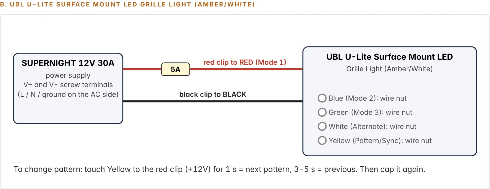
Bench setup B from the project document.
- Fuse 5A (the smallest in the bench kit; the truck gets 3A). Red clip to the light’s red (Mode 1), black clip to black.
- Wire-nut blue, green, white and yellow separately.
- Plug in. The light should flash. Touch yellow to +12V for 1 s to step patterns; 3 to 5 s steps back.
- Optional: move the red clip to blue, then green, to check Modes 2 and 3.
- Both lights together: both reds on +, both blacks on −, the yellows joined so they sync. Put one light’s white on + and they alternate.
- Repeat for the second light.
| Result | Date |
|---|---|
| The lights alternate white and amber on their own | Confirmed 10 Oct 2026 |
| Supplied screws fit the housing snugly | Confirmed 10 Oct 2026 |
| Draw measured | Not yet |
| On the CanTrol, J1-4 | Not yet |
31 October update: CanTrol wiring as approved
Section titled “31 October update: CanTrol wiring as approved”On 31 Oct 2026 I approved the final U-Lite wiring (project document sections 3.1 and 9.2 G). It is now in Upfit Studio and on the generated output plan. Where this differs from the wiring table above, this section wins.
| Wire (both lights) | Function | Goes to | When it is on |
|---|---|---|---|
| Red | Mode 1 | J1 Output 4 through the 3A fuse | Slides 2 and 3 |
| Blue (both joined) | Mode 2 | LED Output 16 | Slide 1 (flashed by the CanTrol), STEADY key |
| Green (both joined) | Mode 3 | LED Output 17 | Slide 1 (flashed by the CanTrol), STEADY key |
| Yellow (both joined) | Pattern / sync | LED Output 24 | RIGHT ALLEY key, momentary pattern step |
| White | Alternate | One light’s white to the same switched 12V; the other taped off | With the red |
| Black | Ground | Frame rail or Ford ground point | Always |
- The yellows now go to a CanTrol output (RIGHT ALLEY) instead of only being joined, so the pattern can be stepped from the control head.
- Which mode the blue and green wires give, and whether the U-Lite holds steady on them, is marked “BENCH” in the plan: confirm on the bench before programming.
- Nothing here is programmed into the CanTrol yet. Draw is still to be measured.
| Part | SKU | Price | Key specs | Source | Status |
|---|---|---|---|---|---|
| UBL U-Lite Surface Mount LED Grille Light, amber/white (x2) | UBL-UL2-SM | $85.50 for two | 350 mA max each, 12V, 6 LEDs | TBD | Bench-tested |
| Black stainless machine screws #6-32 x 3/4" | TBD | About $9.00 (estimate) | Use 4 | TBD | Planned |
| Black stainless #8 fender washers, 1-1/4" across | TBD | About $8.00 (estimate) | Use 4 | TBD | Planned |
| Stainless #6-32 nylon-insert lock nuts | TBD | About $7.00 (estimate) | Use 4 | TBD | Planned |
| 3A blade fuse and sealed in-line ATC holder | TBD | TBD | Within 12" of J1-4 | TBD | Planned |
Open items
Section titled “Open items”- Confirm each light sits centered over a punch plate hole.
- Measure a punch hole and size the fender washer.
- Measure the draw of the pair on the bench.
Sources
Section titled “Sources”- UBL U-Lite installation manual, SKU UBL-UL2-SM, version C.1
- Tyler at UBL support, 7 October 2026 (#6-32 screws)
- F-150 project document, revision 10, sections 6.4, 6.5, 9.3 (U1 to U5) and 10
Changelog
Section titled “Changelog”Added the 31 October approved wiring: red on J1-4, blues on LED Output 16, greens on LED Output 17, yellows on LED Output 24 (RIGHT ALLEY). (build log)
Rollback: Revert the commit that added the 31 October wiring section.
Page published from the 23 October project files.
Rollback: Revert the commit that rebuilt the F-150 section.