
Power, grounds and wire schedule
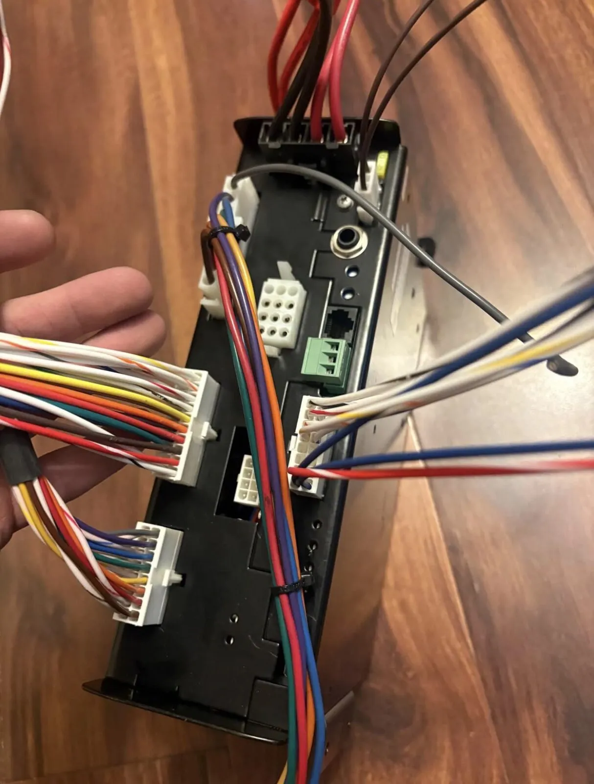
The complete point-to-point wire schedule (about 70 wires), main power on 2 x 8 AWG fused 40A at the battery, the two wiring rules, the fuse table and the under-seat amplifier mount.
Legal notice
Emergency lighting and siren use is regulated by state law and permits. This page documents a personal build and is not legal guidance.
One place that lists every wire in the system, with its source, destination, gauge and protection, so wiring day is a checklist and every circuit can be traced later. Done means every row is installed, labeled, photographed and marked verified.
The two wiring rules (21 Oct)
Section titled “The two wiring rules (21 Oct)”- No ground ever goes on the battery negative post. The 2015+ F-150 measures charge with a sensor on the negative cable (Ford SVE Bulletin Q-231). Use the Ford ground point in that bulletin (M6 bolt, 7 mm eyelet, 9 Nm) or the side of a steel frame rail. The body is aluminum, so no grounds on the cab, bed, fenders, tailgate or radiator support either.
- Amateur radio gets its own battery feed and its own ground, never shared with the CanTrol or its accessory fuse block (Whelen guide 14580G p.1). After install, run every electronic device at once and check for interference.
Safe practice
Section titled “Safe practice”- Battery negative off before any work. Fuse blocks within 2 ft of the battery, fuses out until the end, then inserted one at a time.
- Every pass-through goes through an existing factory firewall grommet or a new rubber grommet, never bare sheet metal. Factory grommets with room: passenger side behind the glove box, and likely driver side behind the pedals (8 Oct).
- Drip loops at the guard. Heat shrink and dielectric grease on exposed joints. No crimp-only joints in the engine bay or grille.
- Loom every run. Cloth harness tape inside the cab so nothing rattles.
- Bench test every product on 12V before any drilling.
Main power
Section titled “Main power”CanTrol main power
- Max input
- 80A through two red wires on the 4-position Molex power plug
- Fuses
- Each red fused 40A separately, within 2 ft of the battery. No circuit breakers. Fuses go in last
- Wire
- 8 AWG per wire (guide p.9 chart)
- Why 8 AWG
- Each red carries half of 80A = 40A; sized at 125% = 50A. At 50A the chart allows 8 AWG to 15.5 ft, 6 AWG to 25 ft, 4 AWG to 39.5 ft. Runs are about 12 ft
- Grounds
- Two black, same gauge, to the Ford Q-231 ground point or a steel frame rail
- Case
- The module case must also be screwed or grounded to the chassis (#10 x 3/4 in screws with lock washers)
- Ignition sense
- J17-7 red/white to an ignition-switched source through a fuse tap (guide item 38)
Source: Whelen CanTrol WC Installation/Operating Guide, form 14580G, p.9 gauge chart
Use 6 AWG only if a measured run is over 15.5 ft. Use pure copper (GXL/TXL), not copper-clad aluminum.
Open item
The ignition sense uses an add-a-circuit fuse tap. Ford’s body builder guidance advises against tapping the fuse panels. The sense wire draws almost nothing, so the electrical risk is low, but it’s against Ford’s written guidance. The choice on record is to keep the fuse tap, picking a slot by meter (live in RUN, dead in OFF, never an airbag, engine or brake circuit). Details on the controller page.
Battery and fuse blocks
Section titled “Battery and fuse blocks”- Battery: Optima Yellow Top DH7, H7 group size, 880 CCA, deep-cycle AGM ($379.99, bought). Suited to running lights and siren with the engine off. Confirm the fit in the 2017 F-150 tray and the terminal orientation before install (to confirm).
- Fuse blocks: two Nilight 6-way ATC/ATO blocks with covers and negative bus, near the battery. One for the CanTrol group, one for accessories. Blade fuses from the Nilight bench kit.
- Accessory feed (P3): about 3 ft of 10 AWG red from the battery, fused at the battery to suit the wire. 10 AWG covers the 30A rocker feed plus the smaller accessory circuits.
Point-to-point wire schedule
Section titled “Point-to-point wire schedule”Gauges are typical short-run values. Confirm them against the Whelen and SpeedTech guides and the measured run lengths.
| ID | From | To | Wire | Protection | Notes |
|---|---|---|---|---|---|
| Main power and grounds | |||||
| P1 | Battery + | CanTrol red power wire 1 (Molex) | Red, 8 AWG | 40A within 2 ft of battery | Through firewall grommet |
| P2 | Battery + | CanTrol red power wire 2 (Molex) | Red, 8 AWG | 40A within 2 ft of battery | Fused separately from P1 |
| G1 | CanTrol black ground 1 | Ford ground point or steel frame rail | Black, 8 AWG | — | Never battery negative |
| G2 | CanTrol black ground 2 | Ford ground point or steel frame rail | Black, 8 AWG | — | Never battery negative |
| P3 | Battery + | Accessory ATC fuse block | Red, 10 AWG | Fuse at battery sized to the wire | Second block near the battery |
| I1 | Ignition-switched source | CanTrol ignition sense, J17-7 red/white | 18 AWG | Fuse tap | System turns off with the key |
| Siren | |||||
| S1 | CanTrol orange speaker lead (high) | Both speaker whites (+) | 16 AWG | — | Parallel, matched polarity |
| S2 | CanTrol brown speaker lead (low) | Both speaker blacks (−) | 16 AWG | — | 5.5 Ω total |
| UBL Color Flood 2.0 light bar | |||||
| C1 | J1-6 | Bar red (power) only | 16 AWG in loom | Bar in-line fuse + output fuse (5A blade allotted) | Slide 2/3, SCENE, all arrows. Never joined to a mode wire |
| C2 | LED Output 2 | Bar blue (right arrow) | 18 AWG | Output fuse | → button, latch |
| C3 | LED Output 1 | Bar white (Mode 3) | 18 AWG | Output fuse | SCENE, latch. Steady white flood |
| C4 | LED Output 9 | Bar yellow (pattern) | 18 AWG | LED output 2.5A | Blank button 2, momentary |
| C5 | Bar black | Frame rail ground | 16 AWG | — | |
| C6 | LED Output 10 | Bar brown (Mode 1) | 18 AWG | Output fuse | Slide 2/3 |
| C7 | J1-1 | Bar orange (Mode 2) | 18 AWG | Output fuse | Slide 3, overrides Mode 1 |
| C8 | LED Output 11 | Bar green (left arrow) | 18 AWG | Output fuse | ← button, latch. ↔ FLASH = center-out |
| UBL U-Lite grille lights | |||||
| U1 | J1-4 | Both reds (Mode 1), spliced | 16 AWG run, 18 AWG leads | 3A in-line within 12 in of J1-4 | Slide 2/3, 0.70A total |
| U2 | J1-4 after the 3A fuse | Left white (Alternate) | 18 AWG | Shares U1 | Makes the pair alternate |
| U3 | Left yellow | Right yellow | 18 AWG | — | Sync |
| U4 | Both blacks | Frame rail ground | 16–18 AWG | — | |
| U5 | Blue, green, right white | Capped, each separately | — | — | Not used |
| Visor light bar | |||||
| V1 | J1-2 | Grand Control Box red | 14 AWG | SpeedTech fuse (keep) | Slide 1/2/3 |
| V2 | Grand Control Box black | Ground point | 14 AWG | — | |
| V3 | Grand Control Box | Visor bar | SpeedTech harness | — | Headliner and A-pillar |
| BooYu rear traffic advisor | |||||
| B1 | J1-3 | BooYu controller + | 14 AWG | 10A in-line ATC | Slide 2/3 |
| B2 | BooYu controller − | Ground point | 14 AWG | — | |
| B3 | BooYu controller | BooYu bar | Supplied cable | — | Rear window |
| UBL rocker panel lights | |||||
| R1 | LED Output 3 | Relay pin 86 | 18 AWG | Output fuse | Slide 3 |
| R2 | Relay pin 85 | Ground | 18 AWG | — | |
| R3 | Accessory fuse block | Relay pin 30 | 12 AWG | 30A | Tag A on the diagrams |
| R4 | Relay pin 87 | Each bar red (Mode 1) | 12–14 AWG | One fuse per bar, sized to draw | Draw not listed |
| R5 | Each bar black | Frame rail ground | 12–14 AWG | — | |
| R6 | Each bar white (Mode 2) | Capped | — | — | |
| R7 | Each bar blue + green | Capped, or tied for center-out | — | — | |
| R8 | Left bar yellow | Right bar yellow + momentary button to fused +12V | 18 AWG | 2A or 3A on the button feed | Pattern/color and sync |
| Speed Turtle EFM 3.0 | |||||
| E1 | LED Output 4 | Harness white (Input 1) | 18 AWG | LED output 2.5A | Slide 3, signal only |
| E2 | LED Output 5 | Harness green (Input 2) | 18 AWG | LED output 2.5A | Blank button 1, latch |
| E3 | BCM J3 and J7 | EFM inline, then vehicle J3 and J7 | Plug-in | — | Battery off first |
| Control and programming | |||||
| H1 | Control head | Module | Whelen head cable | — | Over the headliner and down the driver-side B-pillar |
| H2 | PA microphone | Module | Supplied 20 ft cable | — | |
| H3 | Module USB | Toughbook CF-33 (Whelen Command) | USB 2.0 | — | Programming only |
| Toughbook CF-33 dock, hardwired (planned) | |||||
| L1 | Accessory fuse block | CF-33 vehicle power supply +12V | 14 AWG or per maker | Fuse per dock maker | Under the passenger seat |
| L2 | Power supply − | Ground point | Same as L1 | — | |
| L3 | Ignition-switched source (fuse tap) | Power supply ignition sense | 18 AWG | Fuse tap | Turns off with the key |
| L4 | Power supply output | CF-33 keyboard dock | Supplied cable | — | |
| Strobes N’ More E68Xtreme LED Stick, R/A/W/W/W/W/A/R, on the Federal Signal SLB-FRD15ND kit (planned, not bought) | |||||
| K1 | LED Output 6 | Head 1 (red) + | 18 AWG | LED output 2.5A | Flash only, never steady. About 0.9A max. Wire color per the seller. Inferred |
| K2 | LED Output 7 | Head 2 (amber) + | 18 AWG | LED output 2.5A | Same as K1 |
| K3 | LED Output 8 | Head 3 (white) + | 18 AWG | LED output 2.5A | Same as K1 |
| K4 | LED Output 27 | Head 4 (white) + | 18 AWG | LED output 2.5A | Same as K1 |
| K5 | LED Output 28 | Head 5 (white) + | 18 AWG | LED output 2.5A | Same as K1 |
| K6 | LED Output 29 | Head 6 (white) + | 18 AWG | LED output 2.5A | Same as K1 |
| K7 | LED Output 30 | Head 7 (amber) + | 18 AWG | LED output 2.5A | Same as K1 |
| K8 | LED Output 31 | Head 8 (red) + | 18 AWG | LED output 2.5A | Same as K1 |
| K9 | Stick ground (−) | Ground point | 16 AWG | — | Common ground for all 8 heads. Inferred. Document says “chassis ground near the module”; use the Q-231 point or a frame rail |
| K10 | Module under the rear seat | Rear headliner, center | K1–K9 in loom | — | Up the C-pillar trim to the stick’s 44 in cable; clear of the curtain airbags |
| Putco Work Blade and remote | |||||
| T1 | J1-5 | Bar blue (+12V) | 14 AWG | J1 output fuse (10A) | Slide 2/3, amber-only pattern |
| T2 | Accessory fuse block (tag A) | Remote box red | 18 AWG | 5A ATC | Constant +12V |
| T3 | Remote blue | Bar white (override) | 18 AWG | — | Button A, stopped only |
| T4 | Remote yellow | Bar orange (pattern) | 18 AWG | — | Button B |
| T5 | Remote green, grey | Capped | — | — | C and D not used |
| T6 | Bar red | Capped at the bar | — | — | Auxiliary |
| T7 | Bar black + remote black | Frame rail near the rear bumper | 14 AWG | — | One ring terminal, star washer |
| T8 | Amplifier area and fuse block | Rear bumper | T1 + T2 in 3/8 in loom | — | Existing floor grommet, frame rail |
| T9 | Rear connector | Bar leads | Deutsch DT 4-pin | — | Bar unplugs |
| Rear plate Z-6 heads | |||||
| M1 | LED Output 12 | Both Z-6 reds (Mode 1) | 18 AWG | LED output 2.5A | Slide 2/3 |
| M2 | LED Output 13 | Both Z-6 greens (red brake) | 18 AWG | LED output 2.5A | Brake pop over OBD-II |
| M3 | Truck OBD-II port | CanTrol CANport | CC5K1 kit | — | Data only. Needs CANWCT3 |
| M4 | Both Z-6 blacks | Frame rail near the rear bumper | 18 AWG | — | Can share T7 |
| M5 | Left grey and yellow | Right grey and yellow | 18 AWG | — | Sync |
| M6 | Each brown and blue | Capped separately | — | — | |
| M7 | Amplifier area | Rear bumper, behind the plate | M1 + M2 in the T8 loom | — | Through the bracket grommet holes |
| Front plate Z-6 option (not bought) | |||||
| N1 | LED Output 14 | Both front reds | 18 AWG | LED output 2.5A | Slide 2/3 |
| N2 | LED Output 15 | Both front greens (Super Takedown) | 18 AWG | LED output 2.5A | TAKE DOWN button, latch |
| N3 | Both blacks | Frame rail near the front bumper | 18 AWG | — | |
| N4 | Left grey and yellow | Right grey and yellow | 18 AWG | — | Sync |
| N5 | Amplifier area | Front bumper | N1 + N2 in loom | — | Firewall grommet with the guard wires |
| N6 | Each brown and blue | Capped separately | — | — | |
| Spares | |||||
| X1 | LED Output 32 | Spare | — | — |
The five-modes plan proposes 14 more trigger wires (O1 to O14). They aren’t in this schedule until that plan is decided.
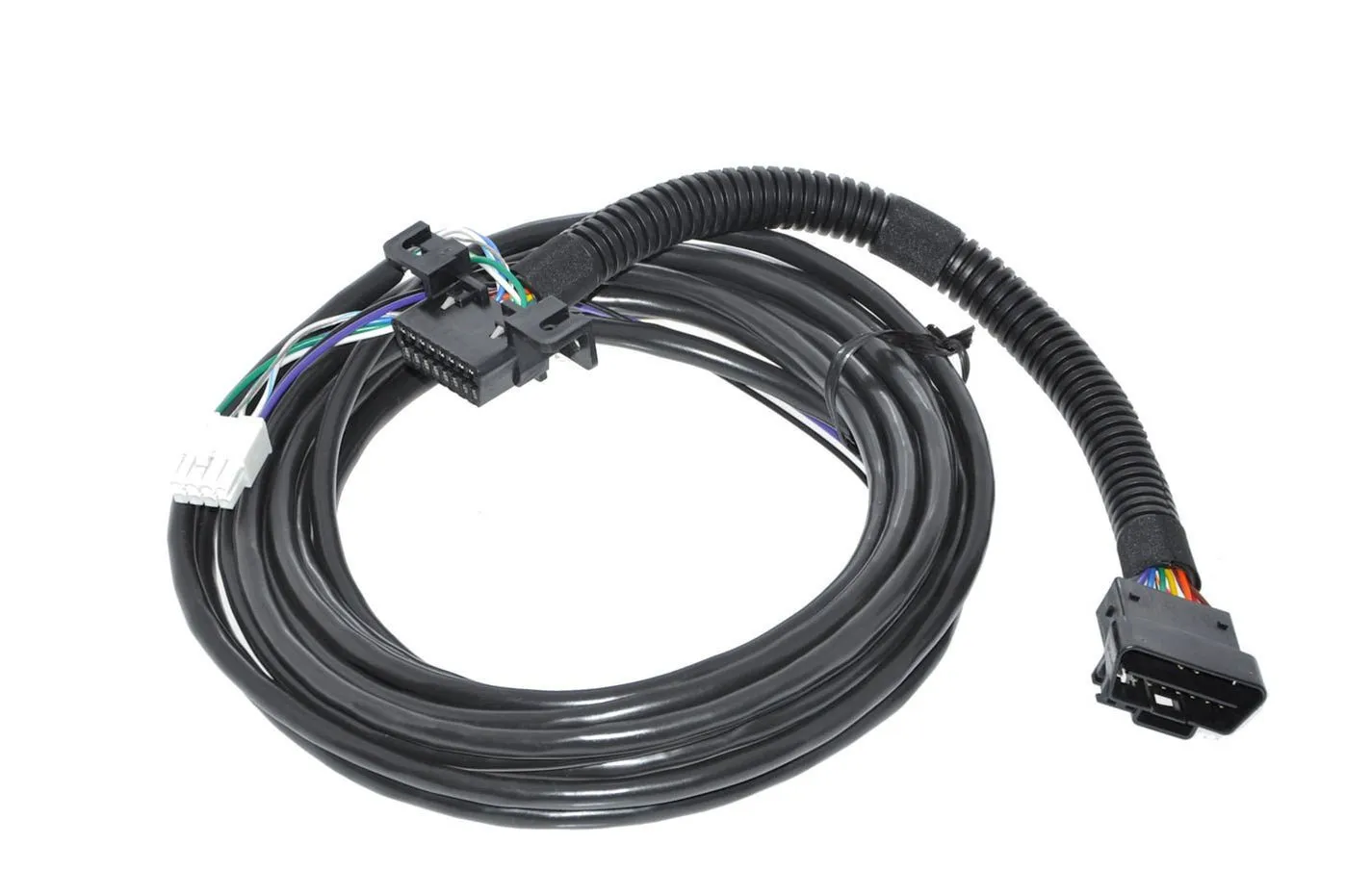
Row M3: the Whelen CC5K1 Ford CANport harness, which arrived 26 Oct. Data only, no power.
Fuses and wire sizes
Section titled “Fuses and wire sizes”| Circuit | Fuse (within 2 ft of source) | Wire |
|---|---|---|
| CanTrol main power (80A max input) | Two reds, each fused 40A at the battery. Fuses in last | 8 AWG per wire (confirmed from the guide chart) |
| Ignition sense (J17-7) | Fuse tap | 18 AWG to an ignition-switched source |
| Siren speakers | None at the speaker | Orange to white (high), brown to black (low), parallel |
| Visor bar via Grand Control Box | SpeedTech’s included fuse, no larger | SpeedTech harness, 14 AWG to J1-2 |
| EFM 3.0 white/green (LED Outputs 4, 5) | LED outputs 2.5A each, 20A group fuse | 18 AWG |
| BooYu controller (J1-3) | About 10A in-line | Size to measured draw |
| UBL rocker bars (relay, coil on LED Output 3) | Size to measured draw, one per bar | 12–14 AWG relay to bars |
| J1 high-current Outputs 1–8 | 10A each, CanTrol internal fuses, 40A combined for all outputs | 14 AWG typical short runs |
| UBL Color Flood 2.0 (red on J1-6) | The bar’s own in-line fuse on red (a 5A blade is allotted for C1 in the parts list) | 16 AWG in loom through the grille |
| UBL U-Lites (J1-4) | 3A in-line within 12 in of J1-4 (UBL), plus the CanTrol output fuse | Extend 18 AWG leads; 16 AWG run |
| Putco remote box | 5A ATC at the accessory block (inferred) | 18 AWG, constant +12V |
| Toughbook CF-33 dock (planned) | In-line at the accessory block, size per the power supply maker | 14 AWG or per maker; 18 AWG ignition sense |
Load budget
Section titled “Load budget”The known loads come to roughly 7.4A: the visor bar under 2.4A, the Color Flood bar at 3.3A max, the U-Lites at 0.70A, and two Z-6 heads under 0.5A each (estimate, not a measurement). The BooYu, the Putco bar and the rocker bars are not yet measured, and the siren adds about 8A per 100W speaker by the 295HFSA6 reference (inferred). The CanTrol’s 40A combined output limit and the 2 x 40A main feed leave room, but the real number comes from the bench.
Amplifier mount under the rear seat (recommended, 8 Oct)
Section titled “Amplifier mount under the rear seat (recommended, 8 Oct)”The CanTrol module goes under the driver-side rear seat. Whelen asks for a dry, cool spot with room around its vents and fans, and for the case to be screwed or grounded to the chassis. This replaced the earlier console-bin plan. It stays dry, out of airbag zones and out of sight, and keeps the console free for the head. The rear seat folds down over an amp-sized box (confirmed 10 Oct).
SIDE VIEW, driver side (front of truck to the left)
ENGINE BAY | firewall control head (overhead console) BATT ── grommet ──────────── driver seat ─────────── rear seat cushion (lifted) 2 red (via 40A fuses) + 2 black ┌──────────────┐ under the driver-side sill trim ────────────► │ AMPLIFIER │ 2–3 in air above └──────────────┘ 1/8 in aluminum plate, 4 fasteners to the floor- Lift the driver-side rear seat cushion. Take out any factory under-seat storage tray and vacuum the floor.
- Set the amplifier in place and check three things: the head cable reaches the control head, the cushion folds down and latches without touching the amp, and nothing blocks the seat latches or seat-belt buckles. Check for a factory subwoofer under the seat.
- Cut a 1/8 in aluminum plate (or 1/4 in HDPE) about 1 in larger than the amp all round. Screw the module to the plate through its mounting holes with lock washers (#10 x 3/4 in), keeping its vents and fans clear.
- Fasten the plate to the floor at four points. Use existing factory bolt points if any line up. Otherwise use self-tapping screws or rivnuts, but first check under the truck so you don’t drill into brake lines, fuel lines or wiring. Seal each hole with silicone. Don’t rely on Velcro or tape alone, because the amp must stay put in a crash.
- Bring the two red power wires (each fused 40A at the battery) and two black grounds through the firewall grommet and back under the driver-side sill trim. Loom them and keep them off sharp edges.
- Run the head cable up the driver-side B-pillar and over the headliner to the overhead console, and the speaker and light outputs forward to the firewall.
- Leave 2 to 3 in of open air above the fins, fold the cushion down, and run the bench checks again before driving.
Open items
Section titled “Open items”- Measure the runs: battery to under the rear seat, battery to the grille, rear seat to the visor.
- Confirm the head cable reaches from the overhead console to the module.
- Confirm the Optima DH7 fit and terminal orientation.
- Measure every unlisted draw and finish the fuse sizes.
- Pick the ignition sense slot by meter.
Sources
Section titled “Sources”- Whelen CanTrol WC Installation/Operating Guide, form 14580G (power, gauge chart p.9, mounting, ignition sense, radio separation p.1)
- Ford SVE Bulletin Q-231 (battery monitoring sensor and ground point)
- F-150 project document, revision 10, sections 9.3, 9.4, 9.5 and 9.6
Changelog
Section titled “Changelog”Added the CanTrol connector photo as the page header and the CC5K1 harness photo at row M3.
Rollback: Revert the commit that made this change.
Dominator K1–K6 replaced by the planned E68Xtreme stick (K1–K10) from the 27 October files; spares now X1 (LED Output 32) only.
Rollback: Revert the commit that added the E68Xtreme.
Page published from the 23 October project files.
Rollback: Revert the commit that rebuilt the F-150 section.